


4 Installation Instructions
Page 12
4.4. Electrical Connections
Unscrew the lid from the BCU and pull it off straight with both hands.
The connection of the thermostat, external signals etc. are described below:
(Wiring max. 2,5 mm
2
.)
1(2), 3(4)
Mains connection 230V
21,22
Contact for optional external error signal (Light/klaxon, max. 253 V / 2 A !)
23, 24
Contact for extra Ventilator
(Switches simultaneously with Ventilator appliance;
max. 253 V / 5 A !
)
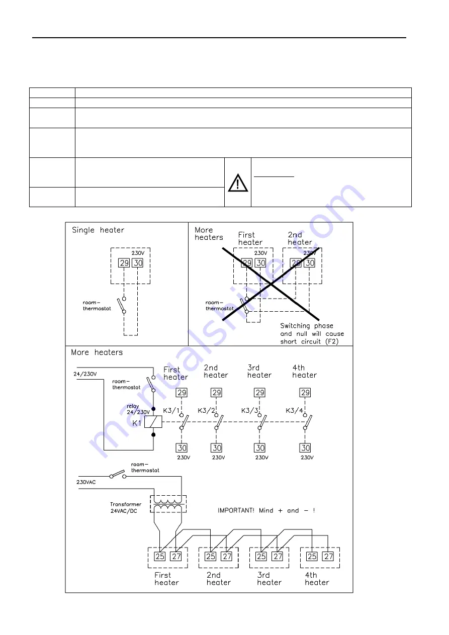
25
26
27
24VAC/DC ( - ) in
Signal “Ventilate” 24VAC/DC( + ) in
Signal “Heating” 24VAC/DC( + ) in
28
29
30
Signal “Ventilate” 230VAC (from 30) in
Signal “Heating” 230VAC (from 30) in
230VAC (for 28 and 29) out
WARNING
Do NOT connect other heaters on
contacts 28 till 32 (Phase sensitive)
31, 32
Optional connection for external reset
button (contact)
Do NOT use different phases.