7 Acceptance/Protection Function Test Guide
7-38
L-PRO 4000 User Manual
D02706R02.30
51 Timing Test
1. Monitor (Timer Stop) on Output Contact 11.
2. Set timer start from single-phase 0.0 A to 6.00 A transition (this equates to
4x pickup).
3. Inject fault.
Observe Relay Target: “51 Trip on A”
51 Directional Test
Settings
• 51 Settings as above
• Line Angle = 80
(i.e. current lags voltage by 80
)
Note: Operating Range = ± 90
from line angle
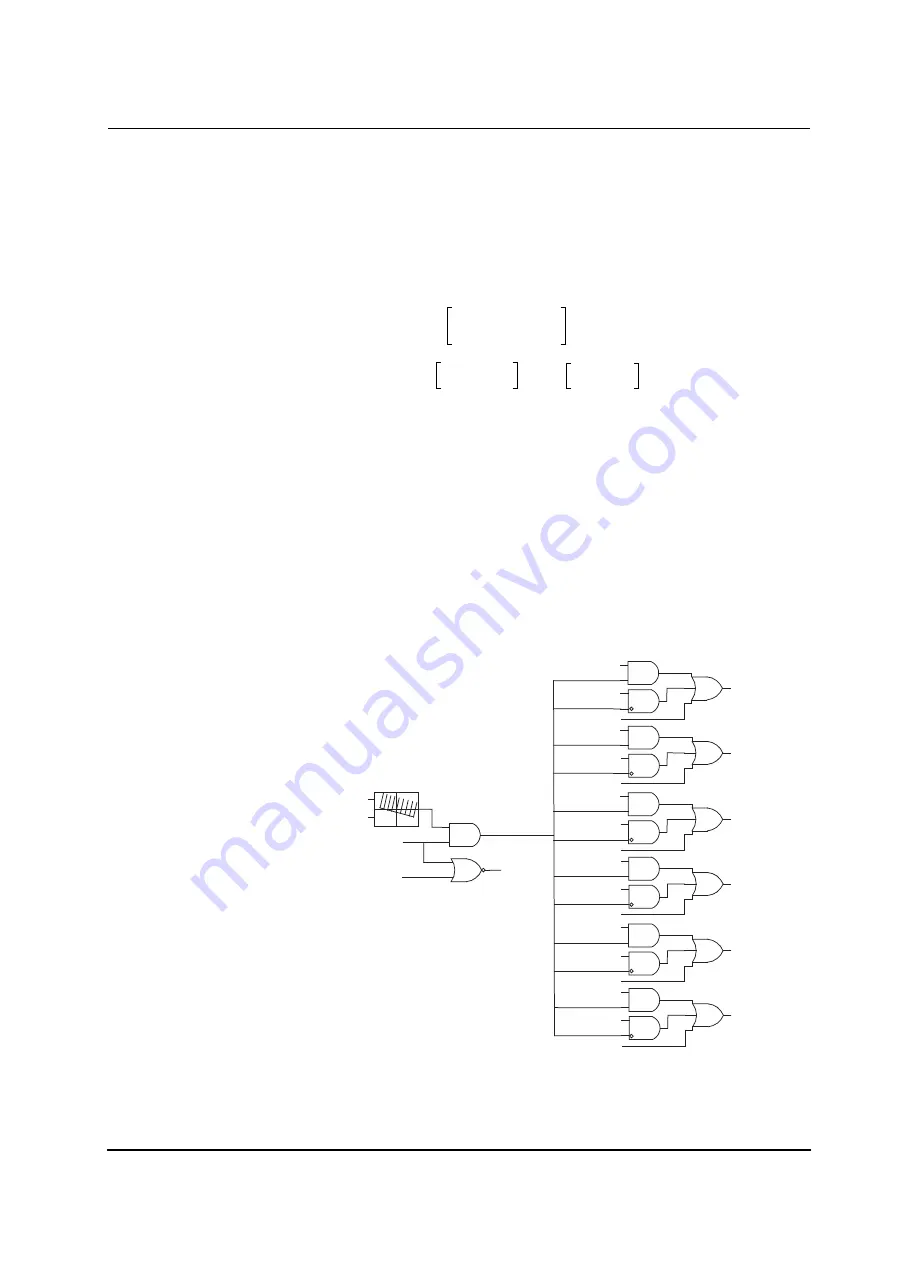
Figure 7.27: Directional Element Logic
Time Delay
(34)
TMS
B
A
I
multiple
p
1
–
-------------------------------------
+
=
0.5
0.00
13.5
4
1
1
–
--------------
+
0.5
0.00 13.5
3
----------
+
2.25
s
=
=
=
FORWARD
REVERSE
Vpos Memory
ILpos
59 Vpos Main (2 volts RMS fixed)
50 ILpos (4% I nominal RMS fixed)
Non-directional
51P Reverse
51P Forward
Non-directional
50P Reverse
50P Forward
Non-directional
51N Reverse
51N Forward
Non-directional
50N Reverse
50N Forward
Non-directional
46-51 Reverse
46-51 Forward
46-50 Reverse
46-50 Forward
51P directional control
50P directional control
50N directional control
51N directional control
46-51 directional control
46-50 directional control
264
265
266
267
268
269
270
271
272
273
274
275
276
277
278
279
280
281
282
283
Non-directional
Non-directional
Summary of Contents for L-PRO 4000
Page 1: ...L PRO 4000 Transmission Line Protection Relay User Manual Version 2 3 Rev 0...
Page 2: ......
Page 4: ......
Page 8: ......
Page 10: ......
Page 14: ......
Page 40: ......
Page 50: ......
Page 116: ......
Page 146: ......
Page 218: ......
Page 252: ...Appendix B IED Settings and Ranges Appendix B 34 L PRO 4000 User Manual D02706R02 30...
Page 260: ......
Page 270: ......
Page 302: ......
Page 308: ......
Page 310: ......
Page 312: ......


