MINI-LINK TN R3 ETSI
4.4.3
Mounting Kits
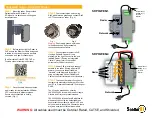
This section describes the mounting kits used for the 0.2 m, 0.3 m and 0.6 m
antennas. A mounting kit consists of two rigid, extruded aluminum brackets
connected with two stainless steel screws along the azimuth axis. The brackets
are anodized and have threaded and unthreaded holes to provide adjustment
of the antenna in azimuth and elevation.
The support can be clamped to poles with a diameter of 50–120 mm or
on L-profiles 40x40x5–80x80x8 mm with two anodized aluminum clamps.
All screws and nuts for connection and adjustment are in stainless steel.
NORD-LOCK washers are used to secure the screws.
6717
Figure 68
Mounting kit for the 0.2 m compact antenna
The 0.2 m compact antenna mounting kit can be adjusted by ±13° in elevation
and by ±90° in azimuth.
6718
Figure 69
Mounting kit for the 0.3 m and 0.6 m compact antennas
The mounting kit for 0.3 m and 0.6 m compact antenna can be adjusted by
±15° in elevation and ±40° in azimuth. Both elevation and azimuth have a
mechanism for fine adjustment.
78
4/1555-CSH 109 32/1-V1 Uen B 2007-09-14
Summary of Contents for MINI-LINK TN R3 ETSI
Page 1: ...MINI LINK TN R3 ETSI Technical Description MINI LINK...
Page 2: ......
Page 3: ...MINI LINK TN R3 ETSI Technical Description...
Page 14: ...MINI LINK TN R3 ETSI 8 4 1555 CSH 109 32 1 V1 Uen B 2007 09 14...
Page 64: ...MINI LINK TN R3 ETSI 58 4 1555 CSH 109 32 1 V1 Uen B 2007 09 14...
Page 110: ...MINI LINK TN R3 ETSI 104 4 1555 CSH 109 32 1 V1 Uen B 2007 09 14...
Page 127: ...Management Figure 92 CLI 121 4 1555 CSH 109 32 1 V1 Uen B 2007 09 14...
Page 128: ...MINI LINK TN R3 ETSI 122 4 1555 CSH 109 32 1 V1 Uen B 2007 09 14...
Page 136: ...MINI LINK TN R3 ETSI 130 4 1555 CSH 109 32 1 V1 Uen B 2007 09 14...
Page 142: ...MINI LINK TN R3 ETSI 136 4 1555 CSH 109 32 1 V1 Uen B 2007 09 14...
Page 148: ......
Page 149: ......


