

LBI-39181
6
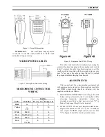
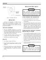
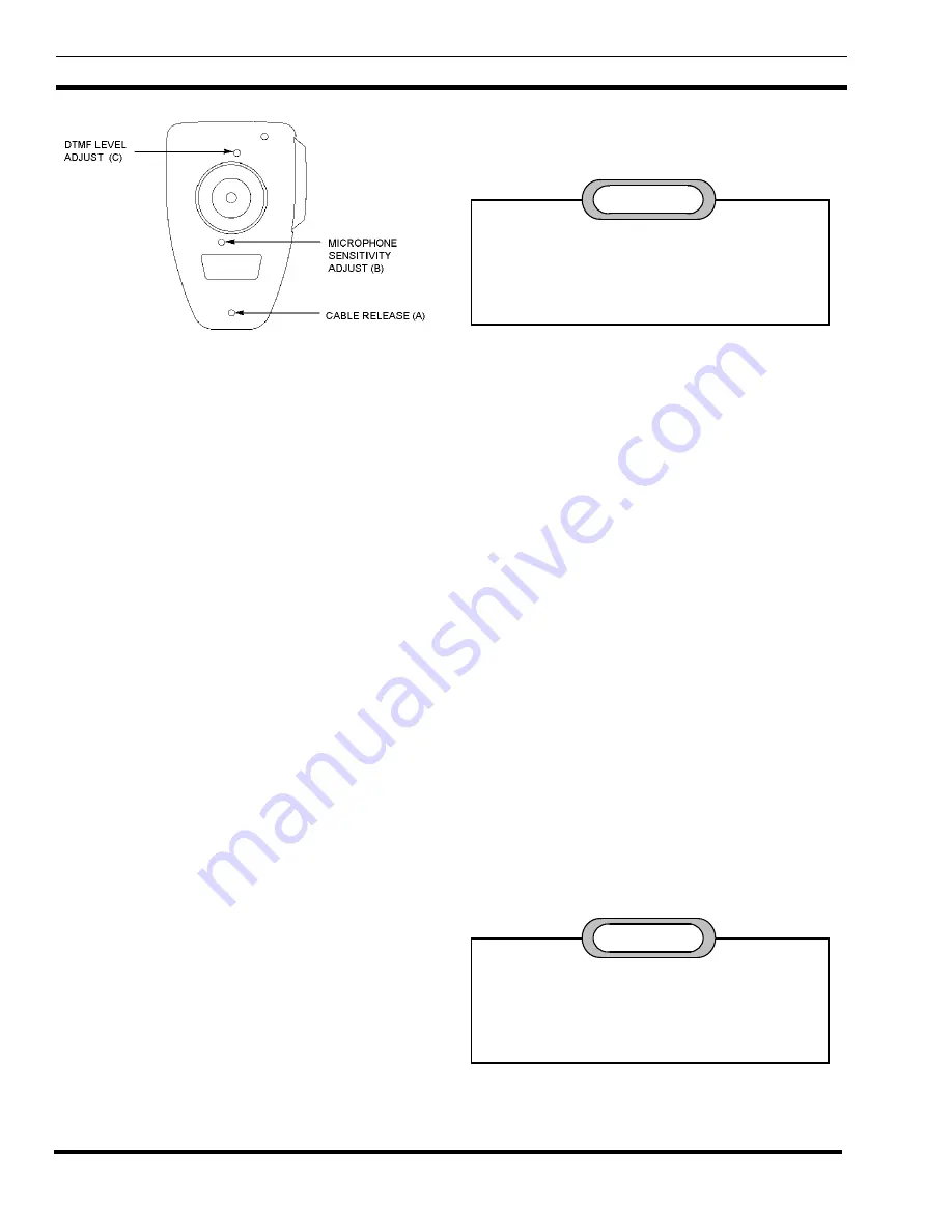
Figure 5 - Microphone Case Rear
OPERATION
Operation of all microphone and DTMF functions
requires that the microphone is connected to the
communications equipment and that the equipment power is
turned on. Power application can be verified by observing
keypad LED backlighting.
VOICE TRANSMISSION
1.
Hold the microphone comfortably in the hand,
positioned so that the Top-Talk Sound Channels at the
top of the case are near the mouth. The clearest sound is
often obtained with the microphone at the corner of the
mouth, with the cable away from the face.
2.
Press the push-to-talk button and make sure the
equipment is in the transmit mode before speaking.
3.
Release the push-to-talk button before dialing.
DIALING
1.
Do not depress the push-to-talk button.
2.
Press the desired keypad buttons in sequence. A high-
pitched tone will confirm that the code has been
transmitted.
3.
When the first keypad button is pushed, the transmitter
is automatically keyed. The transmitter will remain
keyed for approximately 1.5 seconds after the button is
released.
SERVICE INSTRUCTIONS
These microphones contain static-sensitive
semiconductor devices. All work must be performed
at a static-free work station using properly grounded
equipment. Soldering operations must be performed
using a fine-pointed low-wattage soldering iron.
CAUTION
TO DISASSEMBLE THE MICROPHONE
1.
Disconnect the microphone and remove the cable.
2.
Remove the four Phillips-head screws from the back of
the microphone.
3.
Hold the microphone with its back toward you and the
cable connector down. Carefully separate the case back
slightly from the front. Pivot the case back to the right
taking care not to damage any internal leads or
components. Observe that four leads attach the leaf
switch to the boards, and one blue lead attaches the rear
board to the terminal in the center of the case back.
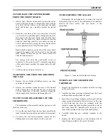
TO DETACH THE CASE BACK AND REAR
PRINTED CIRCUIT BOARD
1. With the partially disassembled microphone face down
on a flat surface and with the cable entry toward you,
locate the multipin connector on the left side between
the center board and the rear board. Carefully pry the
rear board away from the connector on the center board.
(To start the process, the flat blade of a small
screwdriver can be inserted between the terminal pins
connected to the rear board and the connector attached
to the center board.)
2.
Lift the microphone case back and the rear board away
from the center board.
The center board contains static-sensitive
semiconductor devices that can be functionally
damaged by handling. Make certain proper
procedures are followed when working with this
board.
CAUTION