

LBI-39181
5
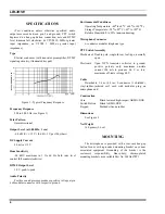
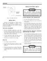
Figure 2 - Overall Dimensions
IMPORTANT:
The microphone hang-up button
is connected to the blue cable conductor for radios with
microphone hang-up sensing.
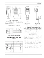
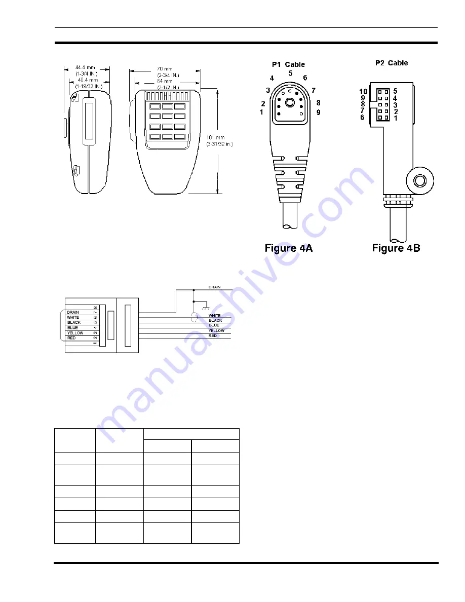
MICROPHONE CABLES
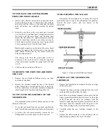
Figure 3 - Microphone End Cable Wiring
MICROPHONE CONNECTOR
WIRING
Part No.
Color
Function
P1 (Fig. 4A)
P2 (Fig. 4B)
Black
A–
7
1
Yellow
—
PTT
3
10
White
Mic Hi
1
4
Red
Switched A+
6
2
Drain
Mic Lo
2
5
Blue
—
CG Dis
8
6
Figure 4 - Equipment End Cable Wiring
The cable is attached to the microphone by inserting the
modular telephone-type plug in the microphone jack until it
locks. To remove the cable from the microphone, insert the
small screwdriver supplied with the microphone in rear case
hole "A" just above the cable jack (see Figure 5) to unlock
the plug and withdraw the plug from the jack.
ADJUSTMENTS
After connection to the communications equipment and
with equipment power turned on, the microphone sensitivity
and DTMF output levels should be adjusted with the
supplied screwdriver as follows.
1.
MICROPHONE SENSITIVITY: Press the push-to-talk
button and speak normally into the microphone while
observing transmitter modulation. Adjust the
microphone sensitivity control (rear case hole "B" in
Figure 5) and repeat the talk test as required.
2.
DTMF OUTPUT: Do not press the push-to-talk button.
Depress and hold down the "#" key for a continuous
tone. Adjust the DTMF output control (rear case hole
"C" in Figure 5) for 60% of rated system deviation.