background image

M4

M4 x 30mm 

[D1]x4


M8

M8 x 25mm 

[D4] x4

M8 x 35mm 

[D5] x4

M8 x 50mm 

[D6] x4

M6

M6 x 15mm 

[D2] x4

M6 x 35mm 

[D3] x4

2.5mm

[C1] x8

10mm

[C2] x4

22mm

[C3] x4

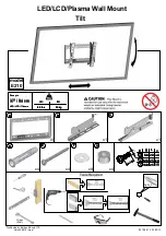
Note: The spacers are shown in accordance with the actual size.

Note: The bolts are shown in accordance with the actual size.

[C] 

Spacers [If necessary]

[D] TV Bolts

Wall Plate Extender

02

x1

Wall Plate

01

x1

M6 Nut

[E2] x2

Bolt

M6X12mm

[E1] x2

[E]

Supplied Parts and Hardware for Step 2

Washer

φ6.5Xφ18X1.8mm

x4

A2

Lag Screw

ST6.3X60mm

x4

A1

Note:  The lag screw is 
shown in accordance 
with the actual size

Supplied Parts and Hardware for Step 3

03

Summary of Contents for INNOVATE EI6171

Page 1: ...nual Thank you for choosing this ERGO INNOVATE product At ERGO INNOVATE we strive to provide you with the best quality products and services in the industry Should you have any issues please don t hes...

Page 2: ...o not use this product for any purpose that is not explicitly speci ed in this manual Do not exceed weight capacity We are not liable for damage or injury caused by improper mounting incorrect assembl...

Page 3: ...t our customer service at support ergo innovate com Please note Not all hardware included in this package will be used Stud Finder Tape Measure Pencil Drill 5 32 in 4mm Wood Drill 3 8 in 10mm Wood Dri...

Page 4: ...the actual size Note The bolts are shown in accordance with the actual size C Spacers If necessary D TV Bolts Wall Plate Extender 02 x1 Wall Plate 01 x1 M6 Nut E2 x2 Bolt M6X12mm E1 x2 E Supplied Part...

Page 5: ...spacers can be used in multi layer If the installation fails after trying various methods please contact customer service at support ergo innovate com Too Short Correct Correct Too Long CAUTION Ensure...

Page 6: ...Alternate Spacer Setups B B1 B2 D1 D3 D5 D6 D C1 C2 C3 C Spacers may be necessary for 2 holes ONLY Option C For TV with A Bump Alternate Spacer Setups B B1 B2 D1 D3 D5 D6 D C1 C2 C3 C 04 03 04 03 04 0...

Page 7: ...ing or VESA Pattern of TV 200X100 600X400mm DO NOT overtighten Tighten only until snug E2 E1 02 01 01 Option A Option B Option D For cable interference or inset holes use spacers C1 C2 and C3 to creat...

Page 8: ...X For wood stud installation follow STEP 3A For concrete installation follow STEP 3B Avoid potential personal injury or property damage DO NOT over tighten the lag screws A1 Tighten the lag screws A1...

Page 9: ...on WARNING Avoid potential personal injury or property damage DO NOT over tighten the lag screws A1 Tighten the lag screws A1 only until the washers A2 are pulled rmly against the wall plate 01 or 01...

Page 10: ...is not less than 2 9 16 in 65mm Never drill into the mortar between blocks 3B 3 Use the hammer to knock anchors A3 into the wall Be sure the anchors A3 are seated ush with the concrete surface A3 3B...

Page 11: ...sen the six preassembled tilt bolts S on both brackets adjust the hooks on the brackets to the desired angle then tighten tilt nuts using a wrench not included and the tilt tension bolts using a Phill...

Page 12: ...the bottom of the TV away from the wall CAUTION Avoid potential personal injury or property damage To prevent the latches from breaking always pull and hold the cords R down while pulling the TV away...

Reviews: