background image

6

6

5

4

1

2

3

5

6

6

5

6

6

5

7

7

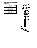
ITEM 

NO.

PART NO

DESCRIPTION

QTY/ASS

1

501301-01

HANDLE BAR

1

2

201203-01

BLUE HANDLE SLEEVE

1

3

501101-01

HANDLE LEFT

1

4

501201-01

HANDLE RIGHT

1

5

503401-01

WASHER (0.8MM)

6

6

402902-01

SCREW FOR HANDLE

6

7

503501-01

SPACER

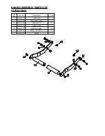
HANDLE ASSEMBLY PARTS LIST

271300-01 REV.01

Summary of Contents for TFA12TE

Page 1: ...TOR INSTRUCTION M ANUA L TFA12TE E Q U A L I Z E R I N T E R N AT I O N A L LT D w w w e q u a l i z e r i n t e r n a t i o n a l c o m E X T E R N A L H Y D R A U L I C F L A N G E A L I G N M E N T...

Page 2: ...G EXTENSION 3 6 CYLINDER ADJUSTMENT SLEEVE 3 7 TOOL CHECKS 3 8 ALIGNMENT 3 9 SECURING THE FLANGE JOINT 4 TOOL MAINTENANCE 4 1 INSPECTION 4 2 CLEANING 4 3 SERVICING 4 4 LUBRICATION PROCEDURE 4 5 STORAG...

Page 3: ...Y Only personnel deemed competent in the use of mechanical and hydraulic equipment should use these tools 2 3 DISCLAIMER Equalizer cannot be held responsible for injury or damage resulting from unsafe...

Page 4: ...MS A CAUTION is used to indicate correct operating or maintenance procedures and practices to prevent damage to or destruction of equipment or other property A WARNING indicates a potential danger tha...

Page 5: ...ld be carried out to determine the most appropriate positioning of the tool on the flange joint The TFA flange alignment tool should always be installed in such a way that the lower flange is closer t...

Page 6: ...foot of the Alignment piston is positioned within the space between the upper and lower faces of the lower flange 3 4 ADJUSTMENT LEG Extend the Adjustment Leg by turning the knurled foot clockwise unt...

Page 7: ...uld cause injury or equipment damage WARNING Do not allow fingers hands or other body parts to come into contact with the flange while actuating the tool Only hold the tool by its designated handles 3...

Page 8: ...structions Actuating the tool will extend the Alignment Piston and align the flanges 3 9 SECURING THE FLANGE JOINT After the flange joint has been aligned it can be secured by installing as many bolts...

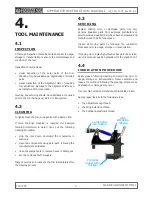
Page 9: ...thread WING EXTENSION THREAD ADJUSTMENT LEG THREAD CYLINDER ADJUSTMENT THREAD 4 TOOL MAINTENANCE 4 1 INSPECTION A thorough inspection should be carried out prior to usage storage or transportation to...

Page 10: ...y to the pump outlet tools in this configuration can be requested from Equalizer The tool is connected to the Equalizer HP hand pump whilst still top side The pump release valve is fully opened and re...

Page 11: ...n forces may be as high as 10 T 12 T 22 T 12 T 12 T 24 T RANGE OF APPLICATION Without Extension Foot DIMENSION MINIMUM MAXIMUM B Bolt Hole Diameter 45 mm M Misalignment 0 mm 65 mm R Rise 150 mm 250 mm...

Page 12: ...ce applied The maximum working pressure of the tool is 510 bar 7400 psi HAND PUMP OPERATION Consult the Instruction Manual for the Equalizer HP Hand Pump supplied in the kit Only use the supplied Hand...

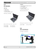
Page 13: ...Product Code MAN_TE_STD 1200 mm x 540 x 170 mm 47 2 x 21 3 x 6 7 Gross kit weight 35 0 kg 77 2 lb 5 4 TOOL DIMENSIONS Tool Weight 21 1 kg 46 5 lb 440 mm 17 3 104 mm 4 1 635 mm 25 0 5 3 KIT CONTENTS T...

Page 14: ...ylinder is fully extended and a small pressure is achieved With the hand pump elevated above the level of the tool and the tool in an upright position open the hand pump release valve causing any air...

Page 15: ...OPERATOR INSTRUCTION MANUAL IM_TFA_12TE_Rev03_A4 TFA12TE FLANGE ALIGNMENT TOOL 15 8 PARTS LISTS SERVICE KITS...

Page 16: ...270900 01 ADJUSTMENT LEG FIXING SHAFT 1 8 272000 01 SIDE SPACER BUSH 2 9 273300 01 SPIRAL CLIP 2 10 070410 01 LHS STICKER 1 11 070411 01 RHS STICKER 1 12 KIT 1215000 01 PROTECTION PAD FINISHED 1 13 M...

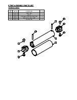
Page 17: ...O PART NO DESCRIPTION QTY ASS 1 270301 09 STRUT TUBE 1 2 270302 09 CLEVIS 2 3 270303 01 M8X12mm BUTTON HEAD HEX SCREW 4 4 273000 01 FOAM GRIP 34MM X 135MM 1 5 273100 01 6MM ROLL PIN 2 STRUT ASSEMBLY P...

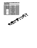
Page 18: ...10 000 PSI 1 2 1320600 01 Cylinder Foot Assembly 1 3 270701 01 CYLINDER ADJUSTING RING 1 4 270501 01 TI CYLINDER SLEEVE 1 5 830313 01 SPIRAL RETAINING RING 1 6 301301 01 M6 SCKT SET SCREW 1 7 300401 0...

Page 19: ...4 3 2 ITEM NO PART NO DESCRIPTION QTY ASS 1 270601 01 CYLINDER FOOT 1 2 270602 01 CYLINDER FOOT PAD 1 3 271800 01 M6 SET SCREW 2 4 501501 01 TFA15TE FOOT SCREW 1 CYLINDER FOOT PARTS LIST 1320600 01 R...

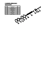
Page 20: ...2 830302 01 PISTON 1 3 830303 01 CYL END CAP 1 4 771110 01 3 8 NPT COUPLER 10kPSI 1 6 KIT 840110 01 WIPER SEAL 1 7 TENSION DIE SPRING 1 8 SPRING LOCK 2 9 M6 CAPSCREW 1 10 O RING 2 11 BACK UP RING 2 1...

Page 21: ...3 2 3 6 5 7 5 6 ITEM NO DESCRIPTION QTY 1 WIPER SEAL 1 2 TENSION DIE SPRING 1 3 SPRING LOCK 2 4 M6 CAPSCREW 1 5 O RING 2 6 BACK UP RING 2 7 SCREW 1 8 M6 GASKET SEAL 1 CYLINDER SERVICE KIT 840110 01 R...

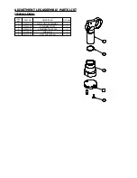
Page 22: ...SCRIPTION QTY ASS 1 270401 01 CLEVIS WELDED ASSEMBLY 1 2 270402 01 ADJUSTMENT FOOT 1 3 270403 01 ADJUSTMENT FOOT PAD 1 4 271500 01 SPIRAL CLIP 1 5 503703 01 M6 CSK HEX SCREW 2 ADJUSTMENT LEG ASSEMBLY...

Page 23: ...SCRIPTION QTY ASS 1 501301 01 HANDLE BAR 1 2 201203 01 BLUE HANDLE SLEEVE 1 3 501101 01 HANDLE LEFT 1 4 501201 01 HANDLE RIGHT 1 5 503401 01 WASHER 0 8MM 6 6 402902 01 SCREW FOR HANDLE 6 7 503501 01 S...

Page 24: ...1 2 3 3 ITEM NO PART NO DESCRIPTION QTY 1 272500 01 PROTECTION PAD FINISHED 1 2 272700 01 FOOT CAP TOWER 1 3 273400 01 M6 CSK HEX SCREW 2 PROTECTIVE PAD SERVICE KIT 1215000 01 REV 01...

Page 25: ...1 ADJUSTMENT ROD 1 2 ADJUSTER BOSS 1 3 NYLON BUSH 1 4 NYLON WASHER 1 5 WING ADJUST DECAL_TFA15TI 1 6 RELEASE KNOB 1 7 EXTERNAL CIRCLIP 1 8 WASHER 10mm ID 2 9 M5 SCKT SET SCREW 4 10 M5x12mm SCKT HEAD C...

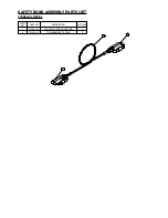
Page 26: ...1 2 2 ITEM NO PART NO DESCRIPTION QTY ASS 1 270801 01 TFA SAFETY BOND WIRE 5MM 1 2 270802 01 TFA KARABINER CE 30KN 2 SAFETY BOND ASSEMBLY PARTS LIST 270800 01 REV 01...

Page 27: ......

Page 28: ...l a y m o r e D r i v e A b e r d e e n S c o t l a n d U K A B 2 3 8 G D t 4 4 0 1 2 2 4 7 0 1 9 7 0 f 4 4 0 1 2 2 4 8 2 3 7 9 1 H o u s t o n O f f i c e 1 3 3 0 Ya l e S t r e e t H o u s t o n T...

Reviews: