background image

20

Troubleshooting

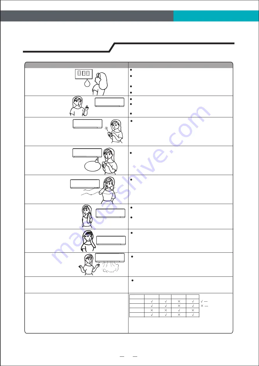
Trouble

Analysis

Does not run

No cooling or 

heating air

Ineffective control

Does not operate 

immediately

Peculiar odor

A sound of 

flowing water

Cracking sound is 

heard

Spray mist from

 the outlet

The running indicator flashes on constantly,


and indoor fan stops.

For the reason that all indoor units use one outdoor 

unit, outdoor unit can only run with same mode

(cooling or heating),so,when the mode you set is 

different from the mode that outdoor is running with, 

mode interfere occurs. Following shows the mode

interfere scene.

The unit is shifting from heating mode to defrost.

The indicator will flash within twelve minutes and

 returns to heating mode.

outdoor unit always run with the mode of first indoor unit that turned on. 

when the setting mode of following indoor unit is interfered with it, 3 beeps 

would be heard, and the indoor unit interfered with the normal running units

would turn off  automatically.  

Is the air filter dirty?

Are the intakes and outlets of the air 

conditioner blocked

Is the temperature set properly

don't run

If the protector trip or fuse is blown.

 If the plug is not properly plugged.

If batteries in the remote controller exhausted.

Please wait for 3 minutes and start again, 

protector device may be preventing unit to work.

.

If strong interference(from excessive static 

electricity discharge, power supply voltage 

abnormality)presents, operation will be 

abnormal. At this  time, disconnect from the 

power supply and connect back 2-3 seconds later.

Changing mode during operation, 3 minutes 

will delay.

This odor may come from another source 

such as furniture, cigarette etc, which is

sucked in the unit and blows out with the air.

Caused by the flow of refrigerant  in the 

air conditioner, not a trouble.

Defrosting sound in heating mode.

The sound may be generated by the expansion 

or contraction of the front panel due to change

of temperature.

Mist appears when the room air becomes 

very cold because of cool air discharged 

from indoor unit during COOLING or DRY

operation mode.

Mode interfere

mode interfere

cooling

cooling

dry

dry

heating

heating

fan

fan

normal

The following cases may not always be a malfunction, please check it before asking for service.

Summary of Contents for EACH12R2W

Page 1: ...much for purchasing our air conditioner Please read this owen s manual carefully before using your air conditioner Model No EACH7R2W EACH9R2W EACH12R2W EACH18R2W EACH24R2W User Manual Multi Zone Indo...

Page 2: ...ructions 1 Care and Maintenance 17 Protection 18 Energy Saving Tips 19 Troubleshooting 20 Safety Precautions 4 Preset 3 Safeguarding the Environment 3 3 Preparation before Use Indoor Unit Installation...

Page 3: ...the distance longer than that length 12 This appliance can be used by children aged from 8 years and above and persons with reduced physical sensory or mental capabilities or lack of experience and k...

Page 4: ...nstalled in accordance with local electrical safety regulations and National Electrical Codes NEC 17 The air conditioner must be installed by professional or qualified persons 20 Regarding to maintena...

Page 5: ...icates that this product should not be disposed with other household wastes throughout the North America To prevent possible harm to the environment or human health from uncontrolled waste disposal re...

Page 6: ...st the power supply cord be broken An electric shock or fire is probably caused by a broken power supply cord Never insert a stick or similar obstacle to the unit Since the fan rotates at high speed t...

Page 7: ...outlet and air can be easily blown to every corner 2 Where piping and wall hole can be easily arranged 3 Keep the required space from the unit to the ceiling and wall according to the installation dia...

Page 8: ...ou might use those special tools listed below Standard Wrench Screw Driver Hex Keys or Allen Wrenches Adjustable Crescent Wrench Torque wrench Drill Drill Bits Manifold and Gauges Vacuum Pump Clamp on...

Page 9: ...iping direction Mounting plate Tapping screw Note The shape of your mounting plate may be different from the one above but the installation method is similar Note it is recommended to install screw an...

Page 10: ...BRACKET DIAGRAMS AND DIMENSIONS Recommended For EACH18R2W EACH24R2W Model WIDTH 629mm 24 8in 200mm 7 9in or more to ceiling 50mm 2in or more to wall 50mm 2in or more to wall Indoor unit outline Pipe...

Page 11: ...S Recommended Decide an installing location for the mounting plate according to the indoor unit location and piping direction Note The shape of your mounting plate may be different from the one above...

Page 12: ...For EACH18R2W EACH24R2W Model WIDTH 629mm 24 8in 10 Installation Instructions MOUNTING BRACKET DIAGRAMS AND DIMENSIONS Recommended FOR the Wooden Wall Mounting Plate...

Page 13: ...or 4 saw the corresponding unloading piece off the indoor unit base Note Both sides drainage structure is standard For both sides drainage structure it can be chosen for right left or both sides drai...

Page 14: ...pe 12 Small pipe Large pipe Thermal insulation tube Power cord Drain hose prepared by user NOTE Dimensions are in mm or inch unless otherwise stated in the table Pipe size Model Liquid Side 1 4 6 or 9...

Page 15: ...ndividually in accordance with the outdoor unit connection Note For some models it is necessary to remove the cabinet to connect to the indoor unit terminal The figures in this manual are based on the...

Page 16: ...g cable to outdoor unit Terminal 1 N 2 L 3 SI For the multi interver For the mono split 1 208 230V Warning Before obtaining access to terminals all supply circuits must be disconnected Terminal Indoor...

Page 17: ...l terminal shall prevail Connecting cable to outdoor unit Terminal 1 N 2 L 3 SI For the multi interver Currently unavailable For the mono split 2 115V Warning Before obtaining access to terminals all...

Page 18: ...nnections are properly insulated 4 Fasten pipes to outside wall when possible 5 Seal and weatherproof wall hole which the interconnecting wires and refrigerant pipes pass through 1 Do all Remote contr...

Page 19: ...ous wash it with a solution of detergent in lukewarm water After cleaning dry well in shade Clean the air filter every two weeks if the air conditioner operates in an extremely dusty environment Stop...

Page 20: ...stop operation After defrosting completes it returns to HEATING mode automatically Note Heating is NOT available for cooling only air conditioner models 1 2 Temperature Cooling operation Heating opera...

Page 21: ...re that obstructs airflow means you could be heating and cooling the back of a chair or the front of a sofa instead of the actual living space Use the swing louvers to help direct the air in the right...

Page 22: ...itioner blocked Is the temperature set properly don t run If the protector trip or fuse is blown If the plug is not properly plugged If batteries in the remote controller exhausted Please wait for 3 m...

Page 23: ...air conditioner you have selected 5 Pipes and Power Connection Cord 6 Drain Hose 4 Front Panel 3 Horizontal Louvers Identification of Parts 21 Indoor unit Outdoor unit 2 Air Filter 1 Remote Controlle...

Page 24: ...al Temperature indicator 1 Running indicator It lights up when the AC is running It flashes during defrosting Timer indicator It lights up during set time Sleep indicator It lights up in sleep mode Co...

Page 25: ...DF series 2 3 5 4 1 8 1 2 3 4 5 8 DE series Display introduction 23 1 2 3 4 5 8 VT series DG Right side series 1 2 3 4 5 8 The symbols may be different from these models but the functions are similar...

Page 26: ...2 3 8 1 8 optional optional Display introduction TD TG TS TT DB DC DH Hidden display DL Middle DJ DK DN series SC series 6 2 7 1 8 1 2 3 4 TL series 1 3 2 4 The symbols may be different from these mod...

Page 27: ...dels but the functions are similar A Emergency buttonA ON OFF To let the AC run or stop by pressing the button QA QB series 1 2 9 10 QA QB series optional optional A TD TL TJ TQ TR TS TT TP TM DB DC D...

Page 28: ...much for purchasing our air conditioner Please read this owen s manual carefully before using your air conditioner Model No EACH7R2W EACH9R2W EACH12R2W EACH18R2W EACH24R2W User Manual Multi Zone Indo...

Page 29: ...3 7 13 5 16 5 5 6 21 21 22 21 Preparaci n antes del uso Preajuste Proteger el entorno Precauciones de seguridad Instrucciones de instalaci n Diagrama de instalaci n Instrucciones del sitio Herramienta...

Page 30: ...eado fijo en conformidad con la normativa nacional 9 Advertencia Riesgo de descarga el ctrica que podr a causar lesiones o muerte Desconecte toda alimentaci n el ctrica remota antes de revisar el apar...

Page 31: ...entaci n est da ado debe sustituirlo el fabricante su agente de mantenimiento o personas cualificadas similares para evitar riesgos 16 El aparato debe instalarse en conformidad con la normativa de seg...

Page 32: ...nda donde compr el aparato Esta marca indica que no se debe eliminar el producto con otros residuos dom stico en la UE Para evitar posibles da os al medio ambiente o a la salud debidos a la eliminaci...

Page 33: ...car una descarga el ctrica o un incendio Nunca inserte palos ni objetos similares en la unidad Debido a la alta velocidad de giro de los ventiladores podr a causar lesiones No repare el aparato usted...

Page 34: ...nst lela en una pared lo bastante fuerte para soportar el peso de la unidad Inst lela en un lugar que no incremente el ruido y las vibraciones del funcionamiento Mant ngala apartada de la luz solar di...

Page 35: ...ci n Llave inglesa est ndar Destornillador Llaves hexagonales o llaves Allen Llave ajustable llave de media luna Llave dinamom trica Taladro y brocas de taladro Colector y man metros Bomba de vac o Pi...

Page 36: ...rnillos como m nimo separados Tornillo autorroscante Placa de montaje Nota La forma de su placa de montaje podr a ser diferente a la mostrada aqu pero el m todo de instalaci n es similar Nota Como se...

Page 37: ...m 2 pulgadas o m s respecto a la pared 50 mm 2 pulgadas o m s respecto a la pared Orificio para tuber a Instrucciones de instalaci n Para la placa de montaje ordinaria DIAGRAMAS Y DIMENSIONES recomend...

Page 38: ...scante Placa de montaje Placa de montaje Pared de hormig n ladrillo Pared de madera Nota La forma de su placa de montaje podr a ser diferente a la mostrada aqu pero el m todo de instalaci n es similar...

Page 39: ...2 pulgadas o m s respecto a la pared 50 mm 2 pulgadas o m s respecto a la pared Orificio para tuber a Instrucciones de instalaci n Para la placa de montaje ordinaria DIAGRAMAS Y DIMENSIONES recomenda...

Page 40: ...eza de descarga a lo largo de la canalizaci n Despu s de conectar las tuber as seg n sea necesario instale la manguera de drenaje A continuaci n conecte los cables el ctricos Despu s de conectarlos en...

Page 41: ...Preste especial atenci n al par permitido mostrado a continuaci n para evitar que las tuber as los conectores y las tuercas c nicas se deformen y resulten da adas Apri telas previamente con los dedos...

Page 42: ...conectarlo Si no fuera posible conecte el aparato a un dispositivo interruptor de dos polos con una separaci n de contacto de al menos 3 mm colocado en una posici n accesible incluso despu s de la ins...

Page 43: ...d externa Terminal 1 N 2 L 3 SI Para multi inverter Para mono split 1 208 230V Advertencia se deben desconectar todos los circuitos de alimentaci n antes de obtener acceso a las terminales Terminal Un...

Page 44: ...valecer Cable de conexi n a la unidad externa Terminal 1 N 2 L 3 SI Para multi inverter Actualmente disponible Para mono split 2 115V Advertencia se deben desconectar todos los circuitos de alimentaci...

Page 45: ...rante y las conexiones est n correctamente aisladas 4 Apriete las tuber as a la pared exterior cuando sea posible 5 Selle e impermeabilice el orificio de la pared por donde pasan los cables de conexi...

Page 46: ...la sombra Limpie el filtro de aire cada dos semanas si el climatizador funciona en un entorno muy polvoriento filtro de aire 1 2 3 1 Abra el panel frontal 2 Presione el asa del filtro suavemente desd...

Page 47: ...o necesita esperar durante 3 minutos Conecte con la fuente de alimentaci n y encienda la unidad inmediatamente se arrancar despu s de 20 segundos En la operaci n deCALENTAMIENTO el aparato se desconge...

Page 48: ...Si hay muebles que obstruyan el flujo de aire quiz se est calentando o enfriando el respaldo de una silla o la parte delantera de una sof en lugar de el espacio de vivienda en s Utilice las rejillas...

Page 49: ...ado est n bloqueadas Est n las ventanas y puertas abiertas no funciona Si el protector se activa o si el fusible se quem Si el conector no est correctamente conectado Si las pilas del control remoto s...

Page 50: ...Identificaci n de piezas Unidad interna Unidad externa ON O FF MODE FA N SW IN G SLE EP SUPER SMART IF EEL DIM MER TIMER ON TIM ER OFF CLOCK 1 6 7 3 4 5 Nombre de la pieza 5 4 3 2 6 2 1...

Page 51: ...roducci n de visualizaci n Indicador NANOE Se ilumina en el modo NANOE 2 Series VQ TE TF DA DG Medio DH DL Derecha Los s mbolos pueden ser diferentes en estos modelos pero las funciones son similares...

Page 52: ...ntroducci n de visualizaci n Serie VT Series DG Derecha Serie DE Serie DF 23...

Page 53: ...Serie TA Serie TQ TR 2 I Series TD TG TS TT DB DC DH monitor oculto DL Medio DJ DK DN 2 Serie TL 2 Los s mbolos pueden ser diferentes en estos modelos pero las funciones son similares Serie SC 24...

Page 54: ...L TJ TQ TR TS TT TP TM DB DC DL DJ DK DX solo 88 Series CA CB Medio Series CA CB derecha Bot n de emergencia Serie QA QB Para encender o apagar el AC pulse el bot n Los s mbolos pueden ser diferentes...

Page 55: ...much for purchasing our air conditioner Please read this owen s manual carefully before using your air conditioner Model No EACH7R2W EACH9R2W EACH12R2W EACH18R2W EACH24R2W User Manual Multi Zone Indo...

Page 56: ...ur l unit int rieure seulement veuillez vous r f rer aux INSTRUCTIONS D UTILISATION ET DE MONTAGE de l unit ext rieure pour l unit ext rieure 1 17 18 19 20 4 3 3 3 7 13 5 16 5 5 6 21 21 Pr Mesures de...

Page 57: ...e est sup rieure cette longueur 11 Cet appareil lectrique n est pas pr vu pour tre utilis par des personnes y compris des enfants avec des capacit s physiques sensorielles ou mentales r duites ou un m...

Page 58: ...tale sous les conditions de tensions de la cat gorie III et cela signifie qu il doit tre incorpor dans le c blage fixe conform ment aux r gles de c blage 18 L appareil lectrique ne devrait pas tre ins...

Page 59: ...g rent avec le tri s lectif des d chets ou la boutique o vous avez achet l appareil lectrique Ce marquage indique que ce produit ne devrait pas tre limin avec d autres d chets domestiques partout en A...

Page 60: ...don d alimentation soit bris Un choc lectrique ou un incendie est probablement caus par un cordon d alimentation bris N ins rez jamais de b ton ou d obstacle similaire dans l unit tant donn que le ven...

Page 61: ...tout o le filtre air peut tre retir sans difficult 5 Maintenez l appareil ainsi que la t l commande 1m 3 28pieds minimum de la t l vision radio etc 6 Maintenez l appareil loign au maximum des lampes f...

Page 62: ...utils sp ciaux list s ci dessous Cl standard Tournevis Cl s hexagonales ou cl s Allen Cl molette r glable en croissant Cl dynamom trique Forets et m ches Collecteur et manom tres Pompe aspirer Pince s...

Page 63: ...imilaire Do 0 0 oo 0 0 LARGEUR A l 0C Remarque Le centre du support de montage peut ne pas tre le centre de l unit int rieure Instructions d installation Installation de l unit int rieure Trou du tuya...

Page 64: ...S DE LA PLAQUE DE MONTAGE Recommand s 200 mm 7 9 pouces ou plus jusqu au plafond Contour de l unit int rieure Trou du tuyau LARGEUR 50 mm 2 pouces ou plus depuis le mur 50 mm 2 pouces ou plus depuis l...

Page 65: ...eure Remarque Il est recommand d installer des chevilles pour le pl tre les blocs de b ton les briques et les murs de ce type SCH MAS ET DIMENSIONS DE LA PLAQUE DE MONTAGE Recommand s Trou du tuyau 9...

Page 66: ...DE MONTAGE Recommand s 200 mm 7 9 pouces ou plus jusqu au plafond Contour de l unit int rieure Trou du tuyau 50 mm 2 pouces ou plus depuis le mur 50 mm 2 pouces ou plus depuis le mur 10 For EACH18R2W...

Page 67: ...embout d vacuation Puis reliez les cordons d alimentation Une fois le branchement effectu enroulez la conduite les cordons et l embout d vacuation dans un isolant thermique Remarque les deux c t s de...

Page 68: ...attache sp cifique Isolation thermique Enroulement dans un ruban adh sif en vinyle Base Attache A Ins rez l attache dans la fente Attache Base Ancrer ici B Appuyez pour bien ancrer l attache sur la b...

Page 69: ...u mod le de base Il se peut donc que la forme de votre climatiseur varie de ceux repr sent s Ch ssis Armoire Panneau avant Borne int rieur Unit int rieure Caract ristiques du c ble Alimentation et c b...

Page 70: ...rne est similaire celle de l unit int rieure Sch ma de c blage Ce sch ma est donn titre purement indicatif et la valeur indiqu e sur la borne pr vaut Pour le multi interverti Pour le mono split 1 208...

Page 71: ...est similaire celle de l unit int rieure Sch ma de c blage Le sch ma est une r f rence seulement et le terminal r el doit pr valoir Pour le multi interverti Pour le mono split 2 115V Attention Avant...

Page 72: ...6 Instructions d installation V rifications de syst me Unit int rieure Unit ext rieure D marrage Essai de fonctionnement 16 30...

Page 73: ...1 2 3 17 Entretien et maintenance 1 teignez d abord le climatiseur 2 Coupez l alimentation en d pla ant la fiche d alimentation a Placez l appareil sur la position a et tirez vers l ext rieur pour re...

Page 74: ...pas disponible sur les mod les qui ne sont pas r versibles 1 2 Temp rature Fonction de refroidissement Fonction de chauffage Fonction de s chage Temp rature int rieure max min Temp rature ext rieure m...

Page 75: ...u mobilier qui g ne le flux d air signifie que vous pourriez chaufferou refroidirl arri rede la chaiseou l avantdu canap au lieu de l espacede vie Utilisezles persiennes pivotantespouraider directerl...

Page 76: ...ur est grill Si la fiche est bien branch e Si les piles de la t l commande sont puis es Attendez 3 minutes et recommencez le dispositif de protection peut emp cher l unit de fonctionner Si vous consta...

Page 77: ...5 Conduits et cordon de raccordement lectrique 6 Embout d vacuation 4 Panneau avant 3 Grilles d a ration horizontale Identification des composants 21 Unit int rieure Unit ext rieure 2 Filtre air 1 T l...

Page 78: ...matiseur fonctionne Il clignote durant le d givrage Indicateur de minuterie Il s allume pendant le temps r gl Indicateur de veille Il s allume en mode veille Indicateur de compresseur Il s allume lors...

Page 79: ...Le symbole peut tre diff rent de ces mod les mais les fonctions sont similaires Pr sentation de l affichage S rie VT S rie DG C t droit S rie DE S rie DF...

Page 80: ...Pr sentation de l affichage optionnel optionnel SC TL Le symbole peut tre diff rent de ces mod les mais les fonctions sont similaires 24...

Page 81: ...t similaires Pr sentation de l affichage S rie QA QB optionnel optionnel S ries TD TL TJ TQ TR TS TT TP TM DB DC DL DJ DK DX Seulement 88 CA CB Milieu S rie CA CB c t droit Bouton d urgence S rie QA Q...

Page 82: ...Emerson Quiet Kool Co Ltd 120 US 46 Parsippany Troy Hills NJ 07054 Toll Free 1 888 493 0305 Version Update 2021 5 0...

Reviews: