background image

Appendix

83

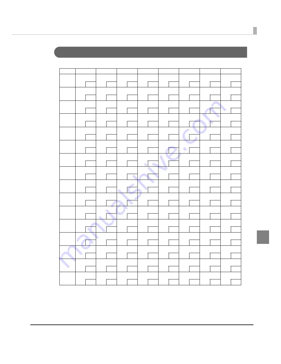
Page 255 (User-Defined Page)

HEX 8 


SP 

128 

SP 

144 

SP 

160 

SP 

176 

SP 

192 

SP 

208 

SP 

224 

SP 

240 


SP 

129 

SP 

145 

SP 

161 

SP 

177 

SP 

193 

SP 

209 

SP 

225 

SP 

241 


SP 

130 

SP 

146 

SP 

162 

SP 

178 

SP 

194 

SP 

210 

SP 

226 

SP 

242 


SP 

131 

SP 

147 

SP 

163 

SP 

179 

SP 

195 

SP 

211 

SP 

227 

SP 

243 


SP 

132 

SP 

148 

SP 

164 

SP 

180 

SP 

196 

SP 

212 

SP 

228 

SP 

244 


SP 

133 

SP 

149 

SP 

165 

SP 

181 

SP 

197 

SP 

213 

SP 

229 

SP 

245 


SP 

134 

SP 

150 

SP 

166 

SP 

182 

SP 

198 

SP 

214 

SP 

230 

SP 

246 


SP 

135 

SP 

151 

SP 

167 

SP 

183 

SP 

199 

SP 

215 

SP 

231 

SP 

247 


SP 

136 

SP 

152 

SP 

168 

SP 

184 

SP 

200 

SP 

216 

SP 

232 

SP 

248 


SP 

137 

SP 

153 

SP 

169 

SP 

185 

SP 

201 

SP 

217 

SP 

233 

SP 

249 


SP 

138 

SP 

154 

SP 

170 

SP 

186 

SP 

202 

SP 

218 

SP 

234 

SP 

250 


SP 

139 

SP 

155 

SP 

171 

SP 

187 

SP 

203 

SP 

219 

SP 

235 

SP 

251 


SP 

140 

SP 

156 

SP 

172 

SP 

188 

SP 

204 

SP 

220 

SP 

236 

SP 

252 


SP 

141 

SP 

157 

SP 

173 

SP 

189 

SP 

205 

SP 

221 

SP 

237 

SP 

253 


SP 

142 

SP 

158 

SP 

174 

SP 

190 

SP 

206 

SP 

222 

SP 

238 

SP 

254 


SP 

143 

SP 

159 

SP 

175 

SP 

191 

SP 

207 

SP 

223 

SP 

239 

SP 

255 


Summary of Contents for TM-T70

Page 1: ...ation when you develop applications Describes setup and instrallation of the product and peripherals Describes how to handle the product Describes features and general specifications for the product Technical Reference Guide 410620803 Rev C Product Overview Setup Application Development Information Handling Appendix ...

Page 2: ...rporation s operating and maintenance instructions Seiko Epson Corporation shall not be liable against any damages or problems arising from the use of any options or any consumable products other than those designated as Original EPSON Products or EPSON Approved Products by Seiko Epson Corporation Trademarks EPSON and ESC POS are registered trademarks of Seiko Epson Corporation in Japan and other ...

Page 3: ... carefully to avoid serious bodily injury CAUTION Provides information that must be observed to prevent damage to the equipment or loss of data Possibility of sustaining physical injuries Possibility of causing physical damage Possibility of causing information loss Provides information that must be observed to avoid damage to your equipment or a malfunction Provides important information and usef...

Page 4: ...ading the outlet may lead to fire Shut down your equipment immediately if it produces smoke a strange odor or unusual noise Continued use may lead to fire Immediately unplug the equipment and contact your dealer or a Seiko Epson service center for advice Never attempt to repair this product yourself Improper repair work can be dangerous Never disassemble or modify this product Tampering with this ...

Page 5: ... not connect cables in ways other than those mentioned in this manual Different connections may cause equipment damage or fire Be sure to set this equipment on a firm stable horizontal surface The product may break or cause injury if it falls Do not use this product in locations subject to high humidity or dust levels Excessive humidity and dust may cause equipment damage or fire Do not place heav...

Page 6: ... of POS systems and development and design of printer applications for developers Manual Content The manual is made up of the following sections Chapter 1 Product Overview Chapter 2 Setup Chapter 3 Application Development Information Chapter 4 Handling Appendix Specifications of Interface and Connector Character Code Tables ...

Page 7: ...13 Power Switch 13 Power Switch Cover 14 Control Panel 14 Connectors 15 Offline 15 Error Status 16 Automatically Recoverable Errors 16 Recoverable Errors 16 Unrecoverable Errors 17 NV Memory Non Volatile Memory 18 User NV Memory 18 NV Graphics Memory 18 Product Specifications 20 Printing Specifications 21 Character Specifications 22 Printable Area 23 Printing and Cutting Positions 24 Paper Specifi...

Page 8: ... the Memory Switches 38 Connecting the Printer to the Host Computer 39 For Serial Interface 39 For Parallel Interface 41 For USB Interface 42 For LAN Interface 44 For Wireless LAN Interface 46 Connecting the Power Supply Unit PS 180 47 Connecting the Power Supply Unit 47 Connecting the Cash Drawer 48 Connecting the Drawer Kick out Cable 48 Setting the Buzzer 49 Application Development Information ...

Page 9: ... Parallel Interface 68 USB Universal Serial Bus Interface 71 Character Code Tables 72 Common to All Pages 72 Page 0 PC437 USA Standard Europe 73 Page 1 Katakana 74 Page 2 PC850 Multilingual 75 Page 3 PC860 Portuguese 76 Page 4 PC863 Canadian French 77 Page 5 PC865 Nordic 78 Page 16 WPC1252 79 Page 17 PC866 Cyrillic 2 80 Page 18 PC852 Latin2 81 Page 19 PC858 Euro 82 Page 255 User Defined Page 83 In...

Page 10: ...10 ...

Page 11: ...speed 170 mm s Graphics are also printed with high speed printing Front operation Easy drop in paper loading Front access operation of the power button and operation panel Front access operation for receipt ejection Software Command protocol is based on the ESC POS Proprietary Command System OPOS ADK and Windows printer driver are available In addition to supporting several kinds of bar code print...

Page 12: ...function Model without the buzzer function Color ECW Epson Cool White EDG Epson Dark Gray Accessories Attachments Roll paper for operation check User s manual Power switch cover Locking wire saddle only for USB interface model Options External power supply Model PS 180 Connector cover Model OT CC70W OT CC70B Protects cables and interface connected to the printer Affixing tapes for fixing the print...

Page 13: ...ply Before turning the printer off it is recommended to send a power off command to the printer If you use the power off sequence the latest maintenance counter values are saved Maintenance counter values are usually saved every two minutes For detailed information about ESC POS commands see the ESC POS Application Programing Guide Manual cutter Roll paper cover Power switch cover Cover open lever...

Page 14: ...eeds the roll paper by one line Holding this button down feeds the roll paper continuously LED PAPER OUT LED Lights when there is no more roll paper or there is little remaining Off when there is a sufficient amount of roll paper remaining Flashes when a self test is in progress ERROR LED Lights or flashes when the printer is offline Lights after the power is turned on or after a reset offline Aut...

Page 15: ...er with the host computer interface Offline The printer automatically goes offline under the following conditions During power on including resetting with the interface until the printer is ready During the self test While roll paper is fed using the FEED button When the printer stops printing due to a paper end if an empty paper supply is detected by the roll paper end sensor or if the driver has...

Page 16: ...on Error LED flash code Recovery measure Roll paper cover open error The roll paper cover was opened during printing Recovers automatically when the roll paper cover is closed Print head temperature error A high temperature outside the head drive operating range was detected Recovers automatically when the print head cools Error Error description Error LED flash code Recovery measure Autocutter er...

Page 17: ...ption Error LED flash code Memory R W error After R W checking the printer does not work correctly High voltage error The power supply voltage is extremely high Low voltage error The power supply voltage is extremely low CPU execution error The CPU is executing an incorrect address Internal circuit connection error Internal circuits are not connected correctly UIB error An abnormal operation occur...

Page 18: ... Use the TM Flash Logo Setup utility for NVRAM to register graphics NV Graphics Print Mode In this mode the printer prints the following Capacity of the NV graphics Used amount of the NV graphics Unused capacity of the NV graphics Number of the NV graphics that are registered Key code number of dots in X direction number of dots in Y direction number of colors to be defined NV graphics data CAUTIO...

Page 19: ...ile pressing the FEED button turn the power on 3 Press the FEED button once 4 Close the roll paper cover 5 After instructions are printed open the roll paper cover 6 Press the FEED button once 7 Close the roll paper cover Turn the power off and on to return to the normal mode ...

Page 20: ...characters and downloaded images NV graphics data 256 KB NV user memory 1 KB Barcode two dimensional code printing UPC A UPC E JAN 8 EAN 8 JAN 13 EAN 13 CODE 39 ITF CODABAR NW 7 CODE 93 CODE 128 PDF417 QR CODE DKD Function 2 drives Supplied voltage 24 VDC 7 Life Mechanism 15 000 000 lines Thermal head 100 million pulses Autocutter 1 5000 000 cuts MTBF 360 000 hours MCBF 52 000 000 lines Temperatur...

Page 21: ...th friction feed Reverse feed is not supported Maximum printable width 72 2 mm 512 dots Character per line Font A 12 24 42 Font B 9 17 56 Maximum print speed 1 High speed mode 170 mm s Low power consumption mode 150 mm s Line spacing 4 23 mm 1 6 Factory setting programmable by command Printing speed may be slower depending on the such items as the data transmission speed High speed mode low power ...

Page 22: ...Font B 9 17 0 987 W 2 397 H mm Number of characters Alphanumeric characters 95 Extended graphics 128 11 pages including user defined page International characters 48 Character structure Font A Initial setting 12 24 including 2 dot spacing in horizontal Font B 9 17 including 2 dot spacing in horizontal Character size Font A Standard 1 69 3 38 mm Double height 1 69 6 77 mm Double width 3 38 3 38 mm ...

Page 23: ...2 is shifted approximately 0 07 mm 0 0028 as shown in the figure below in the paper feed direction In 4 divided energizing the print position within the printable area of the thermal elements for dots 1 to 96 97 to 240 241 to 368 and 369 to 512 is shifted approximately 0 04 mm 0 0016 as shown in the figure below in the paper feed direction OO OO OO OO OO CDWV OO CDWV OO ...

Page 24: ...er width 80 0 5 1 0 mm Paper width 79 5 0 5 mm Specified roll paper type NTP080 80 In U S A Nakagawa Mfg USA Inc In Europe Nakagawa Mfg Europe GmbH In Southeast Asia N A K Mfg Malaysia SDN BHD Original paper TF50KS E Nippon Paper Industries Co Ltd Åj Paper must not be pasted to the roll paper spool The remaining amount of the roll paper when a roll paper near end is detected differs depending on t...

Page 25: ...4V 7 Current consumption at 24V 25 C normal print density Standby Mean Approximately 0 1A Maximum 1A for drawer kick out driving Operating Mean Approximately 1 8A Mean Approximately 1 2A Note When print ratio is approximately 18 Font A 42 columns ASCII character continuous printing for 100 lines repeats 20H 7FH 42 columns ...

Page 26: ...90 RH except for paper Acoustic noise Operating Approximately 55 dB Bystander position Note The values above are measured in the Epson evaluation condition The acoustic noise differs depending on the paper used printing contents or the setting values such as print speed or print density Relative humidity Operating environment range 90 65 10 5 34 40 45 Ambient temperature RH 34 C 90 40 C 65 45 C 50...

Page 27: ...ternal Dimensions and Mass Height Approximately 114 mm 4 49 Width Approximately 125 mm 4 92 Depth Approximately 194 mm 7 64 Mass Approximately 1 8 kg 3 96 lb except for roll paper When the Optional OT CC70 is installed 255 5 114 Unit mm ...

Page 28: ...re to ground for safety Electric characteristics Input conditions input voltage rating 90 to 264VAC 100VAC 10 to 230VAC 15 Frequency rating 50 60 Hz 3 Hz Power consumption rating 100VA Output conditions Output voltage rating 24VDC 5 Output current rating 2 0A Output electric power rating 48VA Output peak current 4 5A Case specifications Dimensions H W D 68 136 32 mm 2 68 5 35 1 26 excluding projec...

Page 29: ...sists of the following sections along with the setup flow of the product and peripherals 1 Installing the Printer page 30 5 Connecting the Power Supply Unit PS 180 page 47 4 Connecting the Printer to the Host Computer page 39 3 Setting the Memory Switches page 38 6 Connecting the Cash Drawer page 48 2 Setting the DIP Switches page 32 ...

Page 30: ...ause the following problems Roll paper near end cannot be detected The roll paper cover will not close after installing roll paper Roll paper cannot be taken out If the printer installation does not fit within the specifications shown in the figure below the following problems may occur Cannot set the roll paper in the printer Cannot cut the paper with the manual cutter Within 3 Within 3 Horizonta...

Page 31: ...ty locations Do not catch cables or foreign matter under the printer Do not put anything that has a force of more than 32 7 N 3 kgf on the top of the printer Affixing Position of DF 10 When you use the affixing tapes for fixing the printer Model DF 10 paste them as shown in the figure below 118 5 Affixing position of the DF 10 ...

Page 32: ...ches using the tip of a tool such as a small screwdriver 4 Attach the DIP switch cover and screw it in place For models with the buzzer function see also Setting the Buzzer on page 49 CAUTION Before you remove the DIP switch cover turn the printer off Otherwise a short circuit may cause the printer to malfunction DIP switch settings are enabled only when the power is turned on or the printer is re...

Page 33: ... 115200 When setting with a command Memory Switch Setting Utility 4800 OFF ON 9600 ON OFF 19200 OFF OFF The transmission speed can be set with a command or the memory switch utility Setting values 2400 4800 9600 19200 38400 57600 115200 The value set with a command or the memory switch utility is enabled only when DIP switches 1 7 and 1 8 are on For other settings the value set with the DIP switch...

Page 34: ...r consumption mode See Selecting the Print Density DIP Switch 2 3 2 4 on page 36 OFF 2 5 Reserved OFF 2 6 Reserved Do not change settings Fixed to OFF OFF 2 7 I F pin 6 reset signal Enabled Disabled OFF 2 8 IF pin 25 reset signal Enabled Disabled OFF For DIP switch 2 1 BUSY condition see also Selecting the BUSY Status on page 37 Do not change the setting of DIP switches 2 2 and 2 6 Otherwise the p...

Page 35: ...tion ON OFF Factory setting 2 1 Handshaking BUSY condition Receive buffer full Offline Receive buffer full OFF 2 2 Reserved Do not change settings Fixed to OFF OFF 2 3 2 4 Selects print density Low power consumption mode See Selecting the Print Density DIP Switch 2 3 2 4 on page 36 OFF 2 5 Reserved OFF 2 6 2 7 Reserved Do not change settings Fixed to OFF OFF 2 8 IF pin 31 reset signal Do not chang...

Page 36: ...rk OFF ON If the print density is set to Darker than standard or Dark level printing speed may be reduced The print density can be set with DIP switches 2 3 2 4 or the customized value See Setting the Memory Switches on page 38 The initial setting of the customized value is Depends on the DIP switch settings If the customized value is changed the value set with the customized value is enabled ...

Page 37: ...ing run Printer status DIP SW 2 1 ON OFF Offline During the period after power is turned on including resetting with the interface to when the printer is ready to receive data BUSY BUSY During the self test BUSY BUSY When the cover is open BUSY During paper feed with the FEED button BUSY When the printer stops printing due to a paper end when printer has run out of roll paper BUSY When an error ha...

Page 38: ...g Utility For detailed information about ESC POS commands see the ESC POS Application Programing Guide The print density can be set with DIP switches 2 3 2 4 or the customized value See Setting the Memory Switches on page 38 The initial setting of the customized value is Depends on the DIP switch settings If the customized value is once changed value set with the customized value is enabled Depend...

Page 39: ...r display DM D is to be connected connect it to the host computer via the serial port Pass through connection This printer is connected to the host computer over the serial interface via a customer display DM D Be sure to install the driver before connecting the printer to the host computer The printer uses the modular connectors specifically designed for the cash drawer Do not connect these conne...

Page 40: ...re the connectors firmly 3 When using interface cables equipped with a grounding line attach the ground line to the screw hole marked FG on the printer 4 Connect the other end of the interface cable to the host computer WARNING Be sure to turn off the power supply for both the printer and host computer before connecting the cables DK 24V FG FG Interface connector Drawer kick out connector Power su...

Page 41: ...g the parallel interface cable 1 Insert the interface cable connector firmly into the interface connector on the connector panel 2 Press down the clips on either side of the connector to lock it in place 3 When using interface cables equipped with a ground line attach the ground line to the screw hole marked FG on the printer 4 Connect the other end of the interface cable to the host computer DM D...

Page 42: ...n only with the UB U01III U02III This printer is connected to the host computer via the USB port When a customer display DM D is to be connected connect it to the printer via the modular cable When connecting a customer display to the printer connect the modular jack from the customer display to the DM connector Also set the communication conditions of the customer display as follows Baud rate 192...

Page 43: ...re below 2 Put the USB cable through the locking wire saddle 3 Connect the USB cable from the host computer to the USB upstream connector Putting the USB cable through the locking wire saddle as shown in the figure below prevents the cable from coming unplugged UB board Locking wire saddle USB cable USB upstream connector ...

Page 44: ...nnect the printer to the host computer via the serial interface CAUTION When LAN cables are installed outdoors make sure devices without proper surge protection are cushioned by being connected through devices that do have surge protection Otherwise the devices can be damaged by lightning Never attempt to connect the customer display cable drawer kick out cable or the standard telephone line cable...

Page 45: ...You can obtain the IP Address Setup Utility for UB E02 and the UB E02 Technical Reference Guide from one of the following URLs or ask your dealer For customers in North America go to the following web site http www epsonexpert com For customers in other countries go to the following web site http www epson pos com 016 14 6 1 70 6 10 75 0 6 10 05 755 10 100BASE T LAN interface connector LED Green L...

Page 46: ...For detailed information about the setup methods see the UB R02 R03 Technical Reference Guide You can obtain the IP Address Setup Utility for UB R02 R03 and the UB R02 R03 Technical Reference Guide from one of the following URLs or ask your dealer For customers in North America go to the following web site http www epsonexpert com For customers in other countries go to the following web site http ...

Page 47: ...the printer and remove the power supply cable from the wall socket WARNING Be sure to remove the power supply unit s cable from the wall socket whenever connecting or disconnecting the power supply unit to the printer Failure to do so may result in damage to the power supply unit or the printer Make sure the wall socket power supply satisfies the rated voltage requirements of the power supply unit...

Page 48: ...e drawer open close signal is used a switch must be provided between drawer kick out connector pins 3 and 6 The resistance of the load such as a drawer kick out solenoid must be 24 Ω or more or the input current must be 1A or less Be sure to use the 24V power output on drawer kick out connector pin 4 for driving the equipment Use a shield cable for the drawer connector cable Two driver transistors...

Page 49: ...awer kick out connector pin 2 Buzzer beeps Buzzer does not beep ON 2 Drawer kick out connector pin 5 Buzzer beeps Buzzer does not beep OFF Since the buzzer drive signal and the cash drawer drive signal are common in the printer do not use the same connector pin numbers to output the signal for the buzzer and the cash drawer For detailed information about ESC POS commands see the ESC POS Applicatio...

Page 50: ...50 ...

Page 51: ...each driver When you newly develop an application Use APD if you want to print TrueType fonts or print much graphics OPOS ADK is recommended for system extensibility An OPOS driver is provided for various peripherals and it is now a POS industry standard It enables efficient POS system establishment reduction of development cost and effective use of application assets When APD is used for your exi...

Page 52: ...he ESC POS Application Programing Guide for more details ESC POS command functions Commands for printing Print and line feed Print and feed n lines Print data in page mode Print and return to standard mode in page mode Commands for line spacing Set line spacing Select default line spacing Commands for print character Select character code table Select an international character set Set right side ...

Page 53: ...width Select justification Set absolute print position Set relative print position Set print area in page mode Select print direction in page mode Set absolute vertical print position in page mode Set relative vertical print position in page mode Commands for bit image Transmit the NV graphic memory capacity Print the graphics data in the print buffer Transmit the remaining capacity of the NV grap...

Page 54: ...of module PDF417 Set the row height PDF417 Set the error correction level PDF417 Select the options PDF417 Store the data in the symbol storage area PDF417 Print the symbol data in the symbol storage area PDF417 Transmit the size information of the symbol data in the symbol storage area QR Code Select the model QR Code Set the size of module QR Code Select the error correction level QR Code Store ...

Page 55: ...rently being used Transmit the remaining capacity of the NV user memory Transmit the key code list Delete all data in the NV user memory Commands for sub functions Initialize printer Transmit printer ID Set horizontal and vertical motion units Select peripheral device Generate pulse to drawer Generate pulse to drawer in real time Execute power off sequence Clear buffer s Enable disable real time c...

Page 56: ...D installation manual APD TM driver manual APD Printer driver specification Status API Reference manual OPOS ADK OPOS This OCX driver can control POS peripherals using OLE technology 1 Because controlling POS peripherals with original commands is not required on the application side efficient system development is possible OPOS installation manual User s guide Application development guide OPOS Ap...

Page 57: ...to develop applications for the LAN interface Download Drivers utilities and manuals can be downloaded from one of the following URLs For customers in North America go to the following web site http www epsonexpert com and follow the on screen instructions For customers in other countries go to the following web site http www epson pos com ...

Page 58: ...g The printer prints current status of the printer on the roll paper When the printer finishes printing the printer status the following message is printed and the PAPER OUT LED flashes The printer is now in the self test wait mode If you want to continue SELF TEST printing Please press FEED button 3 To begin the print test again press the FEED button while the printer is in the self test wait mod...

Page 59: ...cimal numbers and their corresponding characters 4 To quit the hexadecimal dumping mode turn off the printer or press the FEED button three times Printing example If there is no character corresponding to print data is printed If print data is less than one line press the FEED button to print the line Applications that confirm printer status may not work correctly during the hexadecimal dumping mo...

Page 60: ...60 ...

Page 61: ...e roll paper install the roll paper WARNING Do not open the roll paper cover during printing The printer may be damaged Do not touch the manual cutter with your hands when installing or replacing the roll paper Otherwise you may be injured because the manual cutter blade is sharp Use roll paper that meets the printer specification For details about paper specification see Paper Specifications on p...

Page 62: ...62 4 Pull out some roll paper and make sure that the roll paper is set between the paper guides 5 Close the roll paper cover 6 Tear off the roll paper Paper guides ...

Page 63: ...aintain receipt print quality Turn off the printer and open the printer cover Clean the thermal elements of the thermal head with a cotton swab moistened with an alcohol solvent ethanol or IPA CAUTION Do not touch the thermal head See Cleaning the Thermal Head on page 63 because it can be very hot after printing CAUTION After printing the thermal head can be very hot Do not touch it and let it coo...

Page 64: ...reparing for Transport Follow the steps below to transport the printer 1 Turn off the printer 2 Confirm that LED is off 3 Remove the power supply connector 4 Remove the roll paper 5 Pack the printer upright ...

Page 65: ... XON XOFF Signal level MARK 3V to 15V logic 1 OFF SPACE 3V to 15V logic 0 ON Bit length Select one of the following with DIP switch 1 4 7 bit 8 bit Transmission speed bps bits per second Select one of the following with DIP switch 1 7 1 8 4800 9600 19200 115200 bps Select one of the following with commands 2400 4800 9600 19200 38400 57600 115200 bps Parity check Select one of the following with DI...

Page 66: ...e this signal as the printer s reset signal the printer is reset when the signal remains MARK for a pulse width of 1 ms or more 7 SG Signal ground 20 DTR Output 1 When DTR DSR control is selected this signal indicates whether the printer is BUSY SPACE status Indicates that the printer is ready to receive data MARK status Indicates that the printer is BUSY Set BUSY conditions with DIP switch 2 1 2 ...

Page 67: ...receive buffer is released from the buffer full state Transmit Transmit 3 When the printer switches from offline to online Transmit 4 When the printer recovers from an error using some ESC POS commands Transmit XOFF 5 When the receive buffer becomes full Transmit Transmit 6 When the printer switches from online to offline Transmit CAUTION When the printer goes from offline to online and the receiv...

Page 68: ...rol lines in units of four bits a nibble In the byte mode data transfer proceeds by making the 8 bit data lines bidirectional Both modes fail to proceed concurrently in the compatibility mode thereby causing half duplex transmission Mode Communication direction Other information Compatibility mode Host Printer communication Centronics compliant Reverse mode Printer Host communication Assumes a dat...

Page 69: ...ta5 Data5 Data5 8 Host Ptr Data6 Data6 Data6 9 Host Ptr Data7 MSB Data7 MSB Data7 MSB 10 Printer Ack PtrClk PtrClk 11 Printer Busy PtrBusy Data3 7 PtrBusy 12 Printer Perror AckDataReq Data2 6 AckDataReq 13 Printer Select Xflag Data1 5 Xflag 14 Host AutoFd HostBusy k HostBusy 15 NC ND ND 16 GND GND GND 17 FG FG FG 18 Printer Logic H Logic H Logic H 19 GND GND GND 20 GND GND GND 21 GND GND GND 22 GN...

Page 70: ...onal communications cannot take place unless all signal names for both sides correspond to each other Connect all signal lines using a twisted pair cable Connect the return side to the signal ground level Make sure the signals satisfy electrical characteristics Set the leading edge and trailing edge times to 0 5ms or less Do not ignore Ack or BUSY signals during a data transfer Ignoring such signa...

Page 71: ... the host computer Unlike RS232C transmission it cannot spontaneously interrupt data transmission to the host computer The printer has a 128 byte status data buffer Statuses that exceed the buffer capacity are cancelled Overall specifications According to USB 2 0 specifications Transmission speed USB Full Speed 12 Mbps Transmission method USB bulk transmission method Power supply specifications US...

Page 72: ...q 113 2 02 18 34 2 50 B 66 R 82 b 98 r 114 3 XOFF 03 19 35 3 51 C 67 S 83 c 99 s 115 4 EOT DC4 04 20 36 4 52 D 68 T 84 d 100 t 116 5 ENQ NAK 05 21 37 5 53 E 69 U 85 e 101 u 117 6 ACK 06 22 38 6 54 F 70 V 86 f 102 v 118 7 07 23 39 7 55 G 71 W 87 g 103 w 119 8 CAN 08 24 40 8 56 H 72 X 88 h 104 x 120 9 HT 09 25 41 9 57 I 73 Y 89 i 105 y 121 A LF 10 26 42 58 J 74 Z 90 j 106 z 122 B ESC 11 27 43 59 K 7...

Page 73: ...196 212 Σ 228 244 5 à 133 ò 149 Ñ 165 181 197 213 σ 229 245 6 å 134 û 150 a 166 182 198 214 μ 230 246 7 ç 135 ù 151 o 167 183 199 215 τ 231 247 8 ê 136 ÿ 152 168 184 200 216 Ф 232 248 9 ë 137 Ö 153 169 185 201 217 Θ 233 249 A è 138 Ü 154 170 186 202 218 Ω 234 250 B ï 139 155 171 187 203 219 δ 235 251 C î 140 156 172 188 204 220 236 n 252 D ì 141 157 173 189 205 221 Φ 237 253 E Ä 142 Pt 158 174 190...

Page 74: ...1 㩏 197 㩟 213 ټ 229 ᤨ 245 6 ت 134 150 㨰 166 㩀 182 㩐 198 㩠 214 پ 230 ಽ 246 7 ث 135 151 㨱 167 㩁 183 㩑 199 㩡 215 ٽ 231 247 8 ز 136 152 㨲 168 㩂 184 㩒 200 㩢 216 232 ޥ 248 9 ر 137 153 㨳 169 㩃 185 㩓 201 㩣 217 233 Ꮢ 249 A ذ 138 154 㨴 170 㩄 186 㩔 202 㩤 218 234 250 B د 139 155 㨵 171 㩅 187 㩕 203 㩥 219 235 251 C خ 140 ؐ 156 㨶 172 㩆 188 㩖 204 㩦 220 236 252 D ح 141 ؑ 157 㨷 173 㩇 189 㩗 205 㩧 221 237 ੱ 253 E ج 14...

Page 75: ...õ 228 244 5 à 133 ò 149 Ñ 165 Á 181 197 ı 213 Õ 229 245 6 å 134 û 150 a 166 Â 182 ã 198 Í 214 μ 230 246 7 ç 135 ù 151 o 167 À 183 Ã 199 Î 215 þ 231 247 8 ê 136 ÿ 152 168 184 200 Ï 216 Þ 232 248 9 ë 137 Ö 153 169 185 201 217 Ú 233 249 A è 138 Ü 154 170 186 202 218 Û 234 250 B ï 139 ø 155 171 187 203 219 Ù 235 251 C î 140 156 172 188 204 220 ý 236 252 D ì 141 Ø 157 173 189 205 221 Ý 237 253 E Ä 142 ...

Page 76: ...28 244 5 à 133 ò 149 Ñ 165 181 197 213 σ 229 245 6 Á 134 Ú 150 a 166 182 198 214 μ 230 246 7 ç 135 ù 151 o 167 183 199 215 τ 231 247 8 ê 136 Ì 152 168 184 200 216 Ф 232 248 9 Ê 137 Õ 153 Ò 169 185 201 217 Θ 233 249 A è 138 Ü 154 170 186 202 218 Ω 234 250 B Í 139 155 171 187 203 219 δ 235 251 C Ô 140 156 172 188 204 220 236 n 252 D ì 141 Ù 157 173 189 205 221 Φ 237 253 E Ã 142 Pt 158 174 190 206 22...

Page 77: ...196 212 Σ 228 244 5 à 133 Ï 149 165 181 197 213 σ 229 245 6 134 û 150 166 182 198 214 μ 230 246 7 ç 135 ù 151 167 183 199 215 τ 231 247 8 ê 136 152 Î 168 184 200 216 Ф 232 248 9 ë 137 Ô 153 169 185 201 217 Θ 233 249 A è 138 Ü 154 170 186 202 218 Ω 234 250 B ï 139 155 171 187 203 219 δ 235 251 C î 140 156 172 188 204 220 236 n 252 D 141 Ù 157 173 189 205 221 Φ 237 253 E À 142 Û 158 174 190 206 222 ...

Page 78: ... 244 5 à 133 ò 149 Ñ 165 181 197 213 σ 229 245 6 å 134 û 150 a 166 182 198 214 μ 230 246 7 ç 135 ù 151 o 167 183 199 215 τ 231 247 8 ê 136 ÿ 152 168 184 200 216 Ф 232 248 9 ë 137 Ö 153 169 185 201 217 Θ 233 249 A è 138 Ü 154 170 186 202 218 Ω 234 250 B ï 139 ø 155 171 187 203 219 δ 235 251 C î 140 156 172 188 204 220 236 n 252 D ì 141 Ø 157 173 189 205 221 Φ 237 253 E Ä 142 Pt 158 174 190 206 222 ...

Page 79: ... 165 μ 181 Å 197 Õ 213 å 229 õ 245 6 134 150 166 182 Æ 198 Ö 214 æ 230 ö 246 7 135 151 167 183 Ç 199 215 ç 231 247 8 ˆ 136 152 168 184 È 200 Ø 216 è 232 ø 248 9 137 153 169 185 É 201 Ù 217 é 233 ù 249 A Š 138 š 154 a 170 o 186 Ê 202 Ú 218 ê 234 ú 250 B 139 155 171 187 Ë 203 Û 219 ë 235 û 251 C Œ 140 œ 156 172 188 Ì 204 Ü 220 ì 236 ü 252 D SP 141 SP 157 173 189 Í 205 Ý 221 í 237 ý 253 E Ž 142 ž 158...

Page 80: ...5 Е 133 Х 149 е 165 181 197 213 х 229 ї 245 6 Ж 134 Ц 150 ж 166 182 198 214 ц 230 Ў 246 7 З 135 Ч 151 з 167 183 199 215 ч 231 ў 247 8 И 136 Ш 152 и 168 184 200 216 ш 232 248 9 Й 137 Щ 153 й 169 185 201 217 щ 233 249 A К 138 Ъ 154 к 170 186 202 218 ъ 234 250 B Л 139 Ы 155 л 171 187 203 219 ы 235 251 C М 140 Ь 156 м 172 188 204 220 ь 236 252 D Н 141 Э 157 н 173 189 205 221 э 237 253 E О 142 Ю 158 о ...

Page 81: ... L 149 ą 165 Á 181 197 Ň 213 ň 229 245 6 ć 134 l 150 Ž 166 Â 182 Ă 198 Í 214 Š 230 246 7 ç 135 Ś 151 ž 167 Ě 183 ă 199 Î 215 š 231 247 8 ł 136 ś 152 Ę 168 Ş 184 200 ě 216 Ŕ 232 248 9 ë 137 Ö 153 ę 169 185 201 217 Ú 233 249 A Ő 138 Ü 154 SP 170 186 202 218 ŕ 234 250 B ő 139 Ť 155 ź 171 187 203 219 Ű 235 ű 251 C î 140 t 156 Č 172 188 204 220 ý 236 Ř 252 D Ź 141 Ł 157 ş 173 Ż 189 205 Ţ 221 Ý 237 ř 25...

Page 82: ...44 5 à 133 ò 149 Ñ 165 Á 181 197 213 Õ 229 245 6 å 134 û 150 a 166 Â 182 ã 198 Í 214 μ 230 246 7 ç 135 ù 151 o 167 À 183 Ã 199 Î 215 þ 231 247 8 ê 136 ÿ 152 168 184 200 Ï 216 Þ 232 248 9 ë 137 Ö 153 169 185 201 217 Ú 233 249 A è 138 Ü 154 170 186 202 218 Û 234 250 B ï 139 ø 155 171 187 203 219 Ù 235 251 C î 140 156 172 188 204 220 ý 236 252 D ì 141 Ø 157 173 189 205 221 Ý 237 253 E Ä 142 158 174 1...

Page 83: ... SP 229 SP 245 6 SP 134 SP 150 SP 166 SP 182 SP 198 SP 214 SP 230 SP 246 7 SP 135 SP 151 SP 167 SP 183 SP 199 SP 215 SP 231 SP 247 8 SP 136 SP 152 SP 168 SP 184 SP 200 SP 216 SP 232 SP 248 9 SP 137 SP 153 SP 169 SP 185 SP 201 SP 217 SP 233 SP 249 A SP 138 SP 154 SP 170 SP 186 SP 202 SP 218 SP 234 SP 250 B SP 139 SP 155 SP 171 SP 187 SP 203 SP 219 SP 235 SP 251 C SP 140 SP 156 SP 172 SP 188 SP 204 ...

Page 84: ...Ø Å æ ø å É Ä Ö Å Ü é ä ö å ü é ù à ò è ì Pt Ñ ñ É Æ Ø Å Ü é æ ø å ü É Æ Ø Å Ü é æ ø å ü á Ñ é í ñ ó ú á Ñ é ü í ñ ó ú W Ž Š Đ Ć Č ž š đ ć č Ұ ASCII code Hex Country USA France Germany U K Denmark I Sweden Italy Spain I Japan Norway Denmark II Spain II Latin America Korea Slovenia Croatia China ...

Page 85: ......

Page 86: ......

Reviews: