background image

Introduction

8

If fluid enters your eyes, rinse immediately with water. Failure to observe this 
precaution could result in bloodshot eyes or mild inflammation.

If swallowed, induce vomiting and consult a physician immediately.

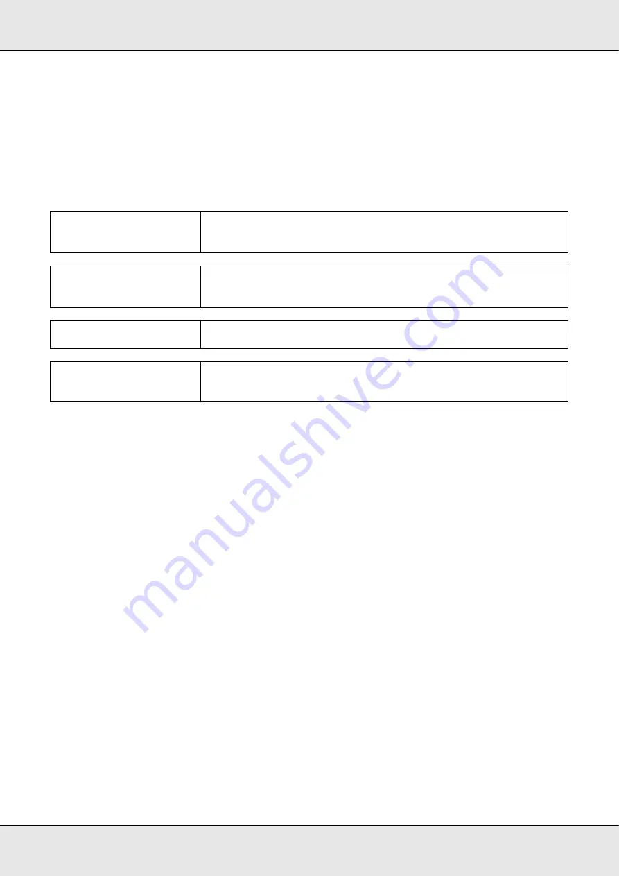
Warnings, Cautions, Important and Notes

w

Warning:

Warnings must be followed to avoid serious bodily injury.

c

Caution:

Cautions must be followed to avoid bodily injury.

Important:

Important must be followed to avoid damage to this product.

Note:

Notes contain useful or additional information on the operation of this 
product.

Summary of Contents for SureColor F7070

Page 1: ... Epson SureColor F7070 User s Guide ...

Page 2: ...s product or excluding the U S failure to strictly comply with Seiko Epson Corporation s operating and maintenance instructions Seiko Epson Corporation shall not be liable for any damages or problems arising from the use of any options or any consumable products other than those designated as Original Epson Products or Epson Approved Products by Seiko Epson Corporation Seiko Epson Corporation shal...

Page 3: ...tivity 19 Superior Ease of Use 20 Notes on Usage and Storage 21 Installation Space 21 Notes When Using the Printer 21 Notes When Not Using the Printer 22 Notes on Handling Ink Packs and Ink Tanks 24 Handling Media 24 Using the Supplied Software 25 Contents of the Software CD 25 Starting EPSON LFP Remote Panel 2 26 Exiting EPSON LFP Remote Panel 2 26 Uninstalling Software 27 Chapter 2 Basic Operati...

Page 4: ...e Print Head 84 Cleaning Preparation and Notes 85 Part Cleaning 86 Cleaning the Wiper Rail 91 Disposing of Waste Ink 93 Replacing the Wiper and Wiper Cleaner 95 Chip Unit Replacement and Ink Refills 98 Time Period for Chip Unit Replacements and Ink Refills 98 Procedure for Chip Unit Replacement and Ink Refills 99 Disposal of Used Consumables 106 Parts That Are Periodically Replaced 107 Chapter 4 U...

Page 5: ...Media Problems 125 Other Problems 128 Chapter 6 Appendix Options and Consumable Products 129 Supported Media 130 Moving and Transporting the Printer 131 Moving the Printer 131 Transport 132 System Requirements 132 Specifications Table 133 Standards and Approvals 134 FCC Compliance Statement 135 Appendix A Where To Get Help Contacting Epson Support 136 Appendix B Software License Terms Open Source ...

Page 6: ...duct near a wall outlet where the plug can be easily unplugged When setting up this product This product s power cord is for use with this product only Use with other equipment may result in fire or electric shock Connect all equipment to properly grounded power outlets Avoid using outlets on the same circuit as copiers or air control systems that regularly switch on and off Avoid electrical outle...

Page 7: ... liquid has entered the product the product has been dropped or the cabinet damaged the product does not operate normally or exhibits a distinct change in performance Do not move the print head by hand otherwise you may damage this product Always turn the product off using the P power button on the control panel When this button is pressed the P power light flashes briefly then goes off Do not unp...

Page 8: ...d induce vomiting and consult a physician immediately Warnings Cautions Important and Notes wWarning Warnings must be followed to avoid serious bodily injury cCaution Cautions must be followed to avoid bodily injury Important Important must be followed to avoid damage to this product Note Notes contain useful or additional information on the operation of this product ...

Page 9: ...s There are two holders one on the left and one on the right See Media Loading and Take Up on page 52 4 Tension bar The tension bar maintains tension to prevent the media from sagging as it is taken up 5 Roll core holder locking screw The locking screws keep the roll core holders in place once they have been attached to the roll core There are two locking screws one on the left and one on the righ...

Page 10: ...charged from this tube Be sure the end of this tube is in the waste ink bottle while the printer is in use 14 Ink tank Holds ink used for printing 15 Slider chip holder See Slider chip holder on page 11 16 Lock lever Raise the levers to unlock the slider for removal when replacing the chip unit Always lower the lock lever after inserting the slider 17 Chip unit check lamp This lamp turns on when a...

Page 11: ... Control panel See Control Panel on page 15 25 Front cover Open when loading media cleaning the inside of the printer or removing jammed media Normally closed when using the printer 1 Slider Attach the chip unit included with the ink pack before refilling the ink See Chip Unit Replacement and Ink Refills on page 98 2 Ink inlet cover Open this cover to refill the ink tank with ink 3 Chip unit A uni...

Page 12: ...d twisted pair cable category 5 or higher 2 Data lamp orange Indicates the network connection status and whether the printer is receiving data On Connected Flashing Receiving data 3 Status lamp green red The color indicates network connection speed Red 100Base TX Green 1000Base T ...

Page 13: ...t edge of the media from touching the print head Position the plates at either side of the media before printing See Loading Media on page 28 3 Cutter groove Pass the blade of a cutter not included down this groove to cut media 4 Pressure rollers These rollers press down on the media during printing See Cleaning the Platen Pressure Rollers and Media Holding Plates on page 79 5 Platen The platen su...

Page 14: ... Roll holder Place media on these holders There are two holders one on the left and one on the right 3 Roll holder fixing screw These screws fix the roll holders in place once the media has been installed There are two screws one on the left and one on the right 4 Roll holder lever If the media to be mounted on the roll holders seems heavy use these levers to raise the media effortlessly to the le...

Page 15: ...nd apply pressure to the roll core 1 P button power button Turns the power on and off 2 P light power light The printer s operational status is indicated by a lit or flashing light On The power is on Flashing The printer is receiving data or performing head cleaning or other operations during shut down Off The power is off ...

Page 16: ...tton to rewind Keep the d button pressed to feed the media Keep the u button pressed to rewind the media Note that when the u button is used to rewind the media will stop when its edge reaches the starting print position Rewind can be resumed by releasing the button and then pressing it again When the menus are displayed these buttons can be used to select menu items and options See Menu Operation...

Page 17: ...y pressing this button and then Z See Cutting Media on page 50 When printing is in progress you can use this button to adjust media feed See Feed Adjustment on page 73 1 Messages Displays the printer s status operation and error messages See When a Message is Displayed on page 120 2 Media info From left to right this display shows the selected media platen gap media width and media remaining If a ...

Page 18: ...cognized or it is not compatible with the printer Or the slider is not locked Check the on screen message The chip unit requires replacement Replace the chip unit with one from a new ink pack As it gets closer to time to replace the chip unit will begin to flash 2 Ink color codes BK Black Y Yellow M Magenta C Cyan 5 Waste ink bottle status Displays the approximate amount of space available in the ...

Page 19: ...rnal diameters of 300 mm 11 8 inches Auto Take up Reel Unit Comes Standard The auto take up reel unit automatically takes up printed media cleanly with no wrinkles You ll find it comes in handy for large textile printing high volume print jobs and continuous overnight printing High Capacity Ink Tanks Included The printer includes high capacity ink tanks for high productivity We also offer 1000 ml ...

Page 20: ...intenance and the printer is constructed with this in mind E Mail Error Warning Notification The EpsonNet Config with Web Browser system built into the printer s network interface offers e mail notification Once configured for e mail notification the printer will send errors and warnings to selected e mail addresses ensuring peace of mind when the printer is left unmanned during overnight operatio...

Page 21: ...e desired results may not be achieved if the temperature and humidity are within the limits for the printer but not within those for the media Be sure the operating conditions suit the media For more information see the documentation supplied with the media Also when operating in dry areas air conditioned environment or under direct sunlight maintain the appropriate humidity Avoid using the printe...

Page 22: ... automatically cleaned at a fixed interval after printing to keep the nozzle from clogging Be sure that the waste ink bottle is installed whenever the printer is on As well as being expended during printing ink is used during head cleaning and other maintenance required to keep the print head in working order Notes When Not Using the Printer If you are not using it note the following points when s...

Page 23: ... may also become wavy or curled causing jams or resulting in the media coming into contact with the print head Remove the media before storing the printer Store the printer after confirming that the print head has been capped the print head is positioned at the far right If the print head is left uncapped for a long time the print quality may decline Close all covers before placing the printer in ...

Page 24: ...p at room temperature for at least 4 hours before using Be sure not to leave any ink in the ink pack when you refill an ink tank Refill the ink tank as soon as possible after opening the ink pack Do not place any objects on top of the ink tank Handling Media Note the following when handling or storing media Media that is in poor condition will not produce good quality prints Be sure to read the do...

Page 25: ...ly dry before folding or stacking as otherwise discoloration or other marks may appear where the prints touch These marks will disappear if the prints are immediately separated and dried but will become permanent if the surfaces are not separated Avoid direct sunlight To prevent discoloration display and store prints as instructed in the documentation supplied with the media Using the Supplied Sof...

Page 26: ...lities Install the Epson communications driver EPSON SC F7000 Series Comm Driver The Epson communications driver is required if the EPSON LFP Remote Panel 2 is to be used to copy media settings It is not a printer driver In addition the software RIP may not display printer status if the Epson communications driver is not installed when the printer is connected to a computer via USB See the softwar...

Page 27: ...l the EPSON communications driver select EPSON SC F7000 Series Comm Driver Printer Uninstall To uninstall EPSON LFP Remote Panel 2 select EPSON LFP Remote Panel 2 4 Select the target printer icon and then click OK 5 Follow the on screen instructions to continue When the delete confirmation message appears click Yes If you are reinstalling the Epson communications driver restart the computer Import...

Page 28: ...l not to trap your hands or fingers when opening or closing the front cover Failure to observe this precaution could result in injury Secure the media in place by the following procedure Injury may occur if the media falls Do not rub your hands along the edges of the media The edges are sharp and can cause injury Important Load media immediately before printing The pressure rollers may crease medi...

Page 29: ...rews and adjust the roll holders so that the gap between the two is wider than the media Center the roll supports between the roll holders cCaution Because the media is heavy it should not be carried by one person When loading or removing the media use at least two persons Important If the right holder handle shaft is not visible rotate the handle forward until it stops The media can not be proper...

Page 30: ... side in If the label does not have a loading position mark it on the label as instructed in the Setup Guide Note Be sure the option selected for Roll Type in the Customize Settings menu matches how the media is rolled Roll Type defaults to Printable Side Out Be sure to select Printable Side In after loading media rolled printable side in For more information see Roll Type on page 70 ...

Page 31: ...ter diameter which is less than 140 mm 5 5 inches lift it up by your hands and place it on the roll holder The roll core will not reach the holder when raised using the roll holder lever 5 Tighten the roll holder screw to fix the roll holder in place 6 Raise the roll holder lever on the right side of the printer to lift the media into position then firmly insert the roll holder ...

Page 32: ...f the roll of media has an outer diameter which is less than 140 mm 5 5 inches lift it up by your hands and place it on the roll holder as described in step 4 7 Tighten the roll holder screw to fix the roll holder in place ...

Page 33: ...the handle until part A in the illustration below is fully inserted 9 Raise the media loading lever Important Once part A is hidden do not turn the handle any further Failure to observe this precaution could damage the roll holder ...

Page 34: ... rollers and lower the media loading lever to hold it in place Confirm that the left edge of the media passes over the center of the square in the label on the loading guide Note Media that is heavy and difficult to unroll can be fed by pressing the drive switch on the left roll holder Printable side out Printable side in ...

Page 35: ...ading lever 14 Pull the media straight forward until the edge is past the label on the bottom side of the eject guide Important Perform steps 11 to 3 in reverse order and repeat the loading process if the left edge of the media is not within the guides Do not attempt to reposition the roll holders while they are inserted in the media ...

Page 36: ...a into the auto take up reel unit see Using the Auto Take up Reel Unit on page 52 Note If you would prefer to print from the very start of the roll press the u button in the control panel to rewind the media slightly Be sure however to stop rewinding before the leading edge of the media is over the cutter groove on the pressure roller side If the leading edge of the media is curled stop rewinding ...

Page 37: ...p them from lifting Important Do not use the media holding plates with media that is more than 0 4 mm 0 02 inch thick The media holding plates could touch and damage the print head Move the media holding plates to the left and right edges of the platen when they are not in use Do not use the media holding plates if the sides of the printed media are smudged or torn Leave left and right margins of ...

Page 38: ...lb The explanation that follows assumes that a lifter is used The following types of lifters can be used Fork or platform thickness 28 mm 1 10 inches or less Fork or platform can be lowered to approx 190 mm 7 5 inches from the floor cCaution Because the media is heavy it should not be carried by one person When loading or removing the media use at least two persons Using a lifter is recommended wh...

Page 39: ...s wider than the media 3 Place the media on a lifter oriented according to how it is rolled see below and move the lift to position the media as indicated by the mark on the label Printable side out Important If the right holder handle shaft is not visible rotate the handle forward until it stops The media cannot be properly loaded if the handle shaft is not visible ...

Page 40: ... the optional heavy roll media system 4 Align the media and the roll holders Note Be sure the option selected for Roll Type in the Customize Settings menu matches how the media is rolled Roll Type defaults to Printable Side Out Be sure to select Printable Side In after loading media rolled printable side in For more information see Roll Type on page 70 ...

Page 41: ...ll core is level with the roll holders 5 Fully insert the left roll holder Next tighten the roll holder screw to fix the roll holder in place 6 Fully insert the right roll holder Next tighten the roll holder screw to fix the roll holder in place 7 Remove the lifter ...

Page 42: ...he media loading lever Important Once part A is hidden do not turn the handle any further Failure to observe this precaution could damage the roll holder If part A is not hidden even after turning the handle until it can no longer be turned return to step 6 and fully press the right unit into the roll core ...

Page 43: ... rollers and lower the media loading lever to hold it in place Confirm that the left edge of the media passes over the center of the square in the label on the loading guide Note Media that is heavy and difficult to unroll can be fed by pressing the drive switch on the left roll holder Printable side out Printable side in ...

Page 44: ...ading lever 14 Pull the media straight forward until the edge has past the label on the left side of the eject guide Important Perform steps 11 to 3 in reverse order and repeat the loading process if the left edge of the media is not within the guides Do not attempt to reposition the roll holders while they are inserted in the media ...

Page 45: ...ia into the auto take up reel unit see Using the Auto Take up Reel Unit on page 52 Note If you would prefer to print from the very start of the roll press the u button in the control panel to rewind the media slightly Be sure however to stop rewinding before the leading edge of the media is over the cutter groove on the pressure roller side If the leading edge of the media is curled stop rewinding...

Page 46: ... Important Do not use the media holding plates with media that is more than 0 4 mm 0 02 inch thick The media holding plates could touch and damage the print head Move the media holding plates to the left and right edges of the platen when they are not in use Do not use the media holding plates if the sides of the printed media are smudged or torn Leave left and right margins of over 10 mm 0 39 inc...

Page 47: ...etup is On the printer will calculate the approximate amount of media remaining based on the length of the roll and the amount used for printing and display this information in the control panel The display gives a rough idea of the amount of media available before printing making it easier to know when media requires replacement In addition a warning will be displayed when the amount of media rem...

Page 48: ...ttons to select Change Settings and press the Z button 2 Select the items you want to change and press the Z button 3 Select the desired option and press the Z button 4 Press the y button to display the dialog shown in step 2 and then press the y button again 5 After confirming that the settings are correct use the d u buttons to select Keep Settings Above and press the Z button 6 If On is selecte...

Page 49: ...is loaded You can print the amount of media remaining on the leading edge of the roll before it is removed from the printer and then enter this number the next time the media is loaded for accurate information on the amount remaining The following section describes how to print the amount of media remaining 1 Confirm that the printer is ready to print 2 Press the M button select Media Remaining in...

Page 50: ...s complete This section described how to use a cutter to cut the media 1 Confirm that the printer is ready to print 2 Press the button and the Z button The printer will feed the trailing edge of the printed media to a position over the cutter groove cCaution When cutting media be careful not to cut your fingers or hands with the cutter or other blades ...

Page 51: ...t of media remaining press the u button to rewind the media so that this information will remain on the roll after the media is cut 3 Remove the media holding plates 4 Cut the media with the cutter Pass the blade of the cutter down the cutting groove ...

Page 52: ...the outside of the roll Clockwise take up places the printed surface on the inside of the roll The explanation that follows uses the supplied auto take up reel unit for illustrative purposes but the same procedure can be followed when using the optional auto take up reel unit for heavy media Important To continue printing after cutting do not rewind the media past the cutter groove on the pressure...

Page 53: ...e roll core holders so that the gap between the two is wider than the media Center the roll supports between the roll holders cCaution Be sure that your hands or hair do not get caught in the auto take up reel unit while it is in operation Failure to observe this precaution could result in injury Perform the following procedure to correctly secure the roll core for the auto take up reel unit into ...

Page 54: ...ll core holder with the right edge of the media and tighten the fixing screw 4 Insert the roll core onto the right holder 5 Insert the left holder into the roll core Slide the holder in until part A in the illustration below is fully inserted ...

Page 55: ...ockwise Take Up 1 Attach the media to the take up roll core Tape the media to the take up roll core in the center and then at the left and right edges Pull the media straight down when taping the left and right edges 2 Press the d button in the control panel to feed enough media for a single wrap around the roll core Important Stop when part A is no longer visible The take up reel unit may not fun...

Page 56: ...ound the roll core Important Confirm that edges of media taken up on the roll core are not misaligned If the edges are misaligned the media that follows cannot be taken up correctly When the edges are misaligned press the Manual switch to the side rewind the media remove the tape and then repeat from step 1 ...

Page 57: ...Basic Operations 57 4 Flip the Auto switch to 5 Lower the tension bar ...

Page 58: ...edia are different the media cannot be taken up correctly If there is slack on one side repeat from step 1 7 Press the d button to feed the media until the take up roll core begins to turn Note As shown in the illustration below you can confirm differences in tension by lightly tapping on both edges of the media Important The auto take up reel unit will not work if the tension bar is raised ...

Page 59: ...up roll core Tape the media to the take up roll core in the center and then at the left and right edges Pull the media straight down when taping the left and right edges 2 Press the d button in the control panel to feed enough media for a single wrap around the roll core ...

Page 60: ...ound the roll core Important Confirm that edges of media taken up on the roll core are not misaligned If the edges are misaligned the media that follows cannot be taken up correctly When the edges are misaligned press the Manual switch to the side rewind the media remove the tape and then repeat from step 1 ...

Page 61: ...Basic Operations 61 4 Flip the Auto switch to 5 Lower the tension bar 6 Confirm that the media is attached without deformation ...

Page 62: ...rocedure for removing media varies depending on whether you are using the installed auto take up reel unit or the optional auto take up reel unit for heavy media Follow the steps below when using the supplied auto take up reel unit When the Heavy Roll Auto Take up Reel Unit is installed See Using the Optional Heavy Roll Media Feeding Unit on page 38 Note As shown in the illustration below you can ...

Page 63: ...the roll at its left end 3 Loosen the left roll core holder fixing screw and remove the roll core holder from the roll 4 Lower the roll onto the roll support 5 To prevent the media from sliding off the roll support the roll at its right end cCaution Because the media is heavy it should not be carried by one person When loading or removing the media use at least two persons Perform the following pr...

Page 64: ...used Fork or platform thickness 28 mm 1 1 inches or less Fork or platform can be lowered to approx 190 mm 7 5 inches from the floor cCaution Because the media is heavy it should not be carried by one person When loading or removing the media use at least two persons Using a lifter is recommended when handling a media that is 40 kg 88 lb or heavier Follow the instructions in the manual when loading...

Page 65: ... 2 Insert the lifter between the media and the auto take up reel unit and adjust the height to support the take up roll 3 Loosen the left roll core holder fixing screw and remove the roll core holder from the roll 4 Loosen the right roll core holder fixing screw and remove the roll core holder from the roll ...

Page 66: ...Print Media Settings A variety of media settings can be optimized for the current media and stored in the printer Once frequently used settings have been stored in a media setting bank they can be recalled to instantly optimize multiple parameters The printer offers a total of 30 media setting banks This section describes how to create media setting banks and the settings that can be stored Parame...

Page 67: ...hoosing a Media Setting Bank 1 After confirming that the printer is ready to print press the Menu button The settings menu will be displayed 2 Select Media Setup and press the Z button 3 Use the d u buttons to select Customize Settings and press the Z button 4 Use the d u buttons to select a media setting bank number between 1 and 30 and then press the Z button Note that any settings already saved...

Page 68: ...ults and enter a correction by hand For more information on feed adjustment see Feed Adjustment on page 73 Platen Gap Adjust the platen gap the gap between the print head and the media if print results are smudged 1 Use the d u buttons to select Platen Gap and press the Z button 2 Use the d u buttons to select the desired setting and press the Z button 3 Press the y button to return to the customi...

Page 69: ... maintain the correct distance between the media and the print head the amount of pressure required varies with the type of media Less suction is used for thin media that would not print or feed correctly at high levels of suction 1 Use the d u buttons to select Media Suction and press the Z button 2 Use the d u buttons to choose a value 3 Select the desired option and press the Z button 4 Press t...

Page 70: ... desired option and press the Z button Tension Measurement Periodically is recommended in most circumstances Choose Off if slack develops in the media or other printing problems occur 1 Use the d u buttons to select Tension Measurement and press the Z button 2 Use the d u buttons to select the desired setting and press the Z button 3 Select the desired option and press the Z button Media Tension I...

Page 71: ...here is a slight gap between the print head and the media the landing sites for the different colors of ink may be affected by humidity temperature inertial forces imparted by the print head or the direction of the print head as it moves from right to left or left to right As a result print results may appear grainy or out of focus When this happens perform Head Alignment to correct the print misa...

Page 72: ...select Manual Uni D or Manual Bi D and press the Z button 7 An alignment pattern will be printed When printing is complete the media will automatically be fed to a position where the pattern is clearly visible Cut the media if necessary See Cutting Media on page 50 8 Check the pattern and select the pattern number that has the least gaps In the following example this would be pattern number 2 Note...

Page 73: ...lor Two methods are available Visually inspect print results and enter a correction by hand Enter a correction during printing and inspect the results Note Feed Adjustment varies with the media used Load the media for which feed adjustment is required under the same conditions as the actual print job For example if you are using the auto take up reel unit for printing the auto take up reel unit sh...

Page 74: ...d u buttons to select Customize Settings and press the Z button 4 Use the d u buttons to select a media setting bank number between 1 and 30 and then press the Z button Note that any settings already saved in the printer will be overwritten 5 Use the d u buttons to select Feed Adjustment and press the Z button 6 Select Manual and press the Z button 7 Use the d u buttons to select a test pattern an...

Page 75: ...nel Using the d u buttons enter the value recorded in step 10 and press the Z button Performing Feed Adjustment During Printing Feed adjustment during printing is recommended for minor banding issues 1 Press the button during printing Note To rewind the media press the u button Stop rewinding before the media is past the cutter groove on the pressure roller side If the leading edge of the media is...

Page 76: ...isfied with the results use the d u buttons to enter an adjustment value 4 Press the Z button when settings are complete Once the feed amount has been adjusted printing will continue at the new value Printable area The gray area in the illustration on the following page shows the printable area The arrow indicates the feed direction The positions of items 1 to 2 are as follows Note The new value i...

Page 77: ...using media holding plates 1 right edge of media Varies with the option selected for Media Size Check On selected for Media Size Check The right edge of the media Off selected for Media Size Check The default right edge position as far as the platen past the center of the label on the loading guide 2 left edge of media Varies with the option selected for Media Size Check On selected for Media Size...

Page 78: ...ns may not conform to the values selected in the document or application If the value selected for Side Margin or Print Start Position is changed documents that fill the printable area will not be printed to the full width of the media ...

Page 79: ...urfaces may be transferred to the media Clean them thoroughly 1 Make sure the printer is turned off and the screen has turned off and then unplug the power cable from the outlet 2 Wait one minute 3 Open the front cover 4 Raise the media loading lever 5 Clean the pressure rollers cCaution Be careful not to trap your hands or fingers when opening or closing the front cover Failure to observe this pr...

Page 80: ... pressure rollers using a soft bristled brush 6 Clean the media holding plates and platen Dampen a soft cloth in water wring it out thoroughly and use it to remove lint and dust from the media holding plates on both the left and right sides and from the platen ...

Page 81: ...n visually inspect the pattern to determine whether there may be faint or missing colors in the preceding or following printout See The Printer Setup Menu on page 115 On Demand Nozzle Pattern Nozzle patterns can be printed as required and inspected visually to determine whether the nozzles are clogged This section explains how to print and inspect a check pattern 1 After confirming that the printe...

Page 82: ...te Head Cleaning Should the nozzle pattern contain faint or missing segments you may be able to unclog the nozzles by cleaning the print head as described below There is no need to clean the head if the print result does not contain faint areas or other color problems You can also clean the head while printing is paused Note however that hues in the printout may change when printing is resumed Not...

Page 83: ... cleaning at an interval selected as described below Periodical Cleaning Head cleaning is performed automatically at selected intervals of 1 to 240 hours See The Printer Setup Menu on page 115 Cleaning Cycle Head cleaning is performed automatically at selected intervals of 1 to 10 pages See The Printer Setup Menu on page 115 This section explains how to clean the head if you find that the nozzles ...

Page 84: ...cleaning level and press the Z button The menu will close when cleaning is complete Print a nozzle pattern and inspect the results to determine whether the problem has been resolved See Checking for Clogged Nozzles on page 81 If you paused the printer in step 1 printing will resume when head cleaning is complete check the printout to confirm whether the problem has been resolved Maintenance Around...

Page 85: ...or polyethylene PE not included Used cleaning sticks wipers and wiper cleaners taken from the printer can be placed here Notes on Cleaning Remove the media from the printer before proceeding Complete the task within 10 minutes to prevent the print head drying out An alarm will sound after 10 minutes Never touch the belts circuit boards or any parts that do not require cleaning Failure to observe t...

Page 86: ...colors in the printout are faint or missing even after the head has been cleaned When the printout is smudged Clean the parts in the following order 1 Print head 2 Wiper 3 Caps 4 Wiper rail Moving the Print Head This section describes how to position the print head for part cleaning Important Be sure to follow the steps below when positioning the print head Moving the print head manually could cau...

Page 87: ...ance covers at each end Cleaning Around the Print Head Inspect the area around the print head and remove any ink stains as described below 1 Use a cleaning stick to wipe the areas of the print head shown in the illustration Important Be sure to use a narrow cleaning stick to clean between the nozzles the four colored areas shown in the illustration Do not touch the nozzle surface Touching the nozz...

Page 88: ...ick If the attachment points do not require cleaning clean the wiper as shown below and proceed to step 7 Important Be sure not to touch the nozzle surface during cleaning Failure to observe this precaution could damage the print head The parts shown below are sensors Be careful not to touch this area with your hands or clean room wipes Failure to observe this precaution could affect print quality...

Page 89: ...Maintenance 89 If there is ink on the attachment points remove the wiper for cleaning Proceed to step 2 2 Remove the wiper Holding the wiper by the attachment point tilt it to the left and lift it out ...

Page 90: ...0 3 Clean the front and back of the wiper with a cleaning stick 4 Clean the bottom of the wiper with a cleaning stick 5 Clean the attachment points with a cleaning stick 6 Return the wiper when cleaning is complete ...

Page 91: ...ick Cleaning the Wiper Rail 1 When Press OK after cleaning is displayed on the control panel press the Z button to move the wiper to the back Important Do not touch the insides of the caps Failure to observe this precaution could deform the affected parts Important Neglecting to clean the wiper rail can impair the performance of the wiper causing product malfunction ...

Page 92: ... Grasp the cleaner as shown and lift it from the printer 3 Clean the area shown in the illustration 4 Replace the wiper cleaner you removed in step 2 to its original position 5 Close the left and right maintenance covers and press the Z button ...

Page 93: ...th water Failure to observe this precaution could result in bloodshot eyes or mild inflammation If problems persist consult with a physician If fluid is swallowed induce vomiting immediately and consult with a physician as soon as possible Important Never remove the waste ink bottle while the head is being cleaned or a head cleaning operation is in progress Failure to observe this precaution could...

Page 94: ...the mouth of the new waste ink bottle and place the waste ink bottle in the holder Tightly seal the lid on the used waste ink bottle Important Only reset the counter when replacing the waste ink bottle Resetting the counter before the waste ink bottle is replaced will result in the printer being unable to accurately track the waste ink level ...

Page 95: ...onfirm that the printer is on and press The Maintenance menu will be displayed 2 Use the d u buttons to select Head Maintenance and press the Z button 3 Press the Z button to move the print head to the cleaning position Important Be sure to confirm that the waste ink tube is inserted in the mouth of the waste ink bottle Ink will spill onto the surrounding area if the tube is not inserted in the bo...

Page 96: ...Maintenance 96 4 Open the right maintenance cover 5 Remove the wiper cleaner Grasp the cleaner as shown and lift it from the printer 6 Insert a new wiper cleaner ...

Page 97: ...tenance 97 Place the wiper cleaner on the attachment point and press down until you hear a click 7 Remove the wiper Holding the wiper by the attachment point tilt it left and lift it out 8 Insert new wiper ...

Page 98: ...k Refills Time Period for Chip Unit Replacements and Ink Refills If the message Chip unit expended is displayed on the control panel this means that the chip unit needs to be replaced soon Obtain an ink pack of the appropriate color as soon as possible You will be unable to print if the chip unit for even one color needs to be replaced If the Chip unit expended message is displayed during a print ...

Page 99: ...of the ink tank cCaution Store ink packs in a location out of reach of children Wear protective eyewear and gloves when refilling ink Be sure to read the Material Safety Data Sheet MSDS before using ink packs You can download it at your local Epson Web site Should ink contact your skin or enter your eyes or mouth immediately take the following actions If fluid adheres to your skin immediately wash...

Page 100: ...ining ink level is 70 mm 2 8 inches or less Proceed to step 2 Important Epson recommends the use of genuine Epson ink packs Epson cannot guarantee the quality or reliability of non genuine ink The use of non genuine ink may cause damage that is not covered by Epson s warranties and under certain circumstances may cause erratic printer behavior Information about non genuine chip unit status may not...

Page 101: ...tating Refill Ink Tank it is time to replace the ink tank We recommend replacing the ink tank at this time Replacements and repairs will be provided for a fee During replacements and repairs the ink in the ink tank is discarded This is necessary because fine dirt dust and other foreign bodies in the ink cause the ink tank to malfunction The ink tank replacement interval depends on the usage enviro...

Page 102: ...ve the chip unit from the slider 5 Attach the chip unit supplied with the new ink pack to the slider Check to confirm that the color of the label on the slider matches the color of the label on the chip unit when installing ...

Page 103: ... lower the lock lever 7 Shake the new ink pack horizontally for approximately 5 cm 2 inches left and right for 5 seconds approximately 15 times Important Do not push the slider in with too much force Failure to observe this precaution could damage the printer ...

Page 104: ...Maintenance 104 8 Open the slider ink inlet cover 9 Remove the ink inlet cap from the ink tank 10 Cut or tear off the ink pack spout opening 11 Fill the ink tank with the ink from the ink pack ...

Page 105: ...nlet groove and slowly tilt to pour out the ink Important Get all the ink out of the ink pack so that there is none remaining Do not use the ink in an ink pack to refill multiple ink tanks This can prevent the proper display of messages from the remaining ink warning system ...

Page 106: ...k on the ink tank 13 Close the slider ink inlet cover Disposal of Used Consumables Dispose of used ink packs and chip units as well as printed media following local laws and regulations for example by consigning waste to industrial waste disposer ...

Page 107: ...cement The time until the following parts need to be replaced depends on the conditions of use Print head Carriage encoder Ink holder Damper kit Pump cap Ink supply tank The part life varies with operating conditions Base the decision to replace the print head on the quality of the print results ...

Page 108: ...u 108 Chapter 4 Using the Control Panel Menu Menu Operations The menus are used as shown below Menu List The following items and parameters can be set and executed in the Menu See the reference pages for more details on each item ...

Page 109: ... in the entries for RIP settings and media setting banks 1 to 30 RIP Settings Platen Gap 1 5 2 0 2 5 Head Alignment Input thickness Manual Uni D Manual Bi D Roll Type Printable Side Out Printable Side In Tension Measurement Periodically Every Page Off Media Tension 0 to 40 1 to 30 media setting bank number Setting Name Up to 22 half size characters Feed Adjustment Manual Platen Gap 1 5 2 0 2 5 Hea...

Page 110: ...See The Maintenance Menu on page 117 Nozzle Check Print Cleaning All Nozzles Execute Light Execute Medium Execute Heavy Selected Nozzles Execute Light Execute Medium Execute Heavy Head Maintenance Move Head Waste Ink Counter Print Logs See The Print Logs Menu on page 117 Print Job Log Sheet Print Show Total Prints XXXXXXm2 XXXXXX ft2 Printer Status See The PrinterStatus Menu on page 118 Print Stat...

Page 111: ...Length Remaining Alert and Print Remaining Length options are available when On is selected The display panel shows the amount of media remaining based on the value selected for Length and the amount of media used during printing Off Length 5 0 to 999 5 m 15 to 3000 ft Enter a value for overall roll length between 5 0 and 999 5 m 15 to 3000 ft You can set in 0 5 m 1 ft increments Remaining Alert 1...

Page 112: ...Gap 1 5 Change Platen Gap the gap between the print head and the media for the media setting bank selected in the software RIP The default setting of 1 5 is recommended in most situations Choose 2 0 if printout is scratched or smudged Select 2 5 only if print results are still smudged when 2 0 is selected Choosing a larger gap than required may result in ink stains inside the printer reduced print...

Page 113: ...ange as follows depending on the Tension Measurement setting Periodically Every Page Level 28 Off Level 39 Item Parameter Explanation Setting Name Assign the media setting bank a name up to 22 half size characters long Using distinctive names makes it easier to select banks for use Feed Adjustment Manual Use this option if banding horizontal banding lines or strips of uneven color persists after h...

Page 114: ...f Choose the number of times each line is printed 2 to 8 Roll Type Printable Side Out Choose Printable Side Out or Printable Side In according to how the media is rolled Printable Side In Tension Measurement Periodically Choose Periodically or Every page to have the printer automatically monitor and adjust media tension during printing for optimal results Off to disable automatic tension adjustmen...

Page 115: ...ct Off the edges of the media Try Off if the printer displays a Media Size Error when the media is correctly loaded Note however that the printer may print beyond the edges of the media when Off is selected Ink used outside the edges of the media will stain the inside of the printer We generally recommend to operate with this setting set to On Off Media End Check On Choose whether the printer auto...

Page 116: ... that even when Off is selected for Periodical Cleaning the printer will automatically clean the print head at a fixed interval after printing to keep the nozzle from clogging Medium Heavy Power Cleaning Cycle Off Choose the frequency with which the printer performs auto head cleaning never Off or once every 1 to 10 pages The cleaning cycle will not be performed while Off is selected Select 1 to 1...

Page 117: ... used Execute Medium choose Execute Heavy See Head Cleaning on page 82 Selected Nozzles Execute Light Execute Medium Execute Heavy Head Maintenance Move Head Position the print head for maintenance Perform such maintenance as cleaning the wiper caps and the area around print head only after using this option to position the head for cleaning Moving the print head manually could cause malfunction S...

Page 118: ...ion XXXXXXX X_XX XXXX View the printer Firmware Version Item Parameter Explanation IP Address Setting Auto Choose whether IP addresses are obtained automatically Auto or manually Panel using DHCP If Panel is selected enter an IP address subnet mask and defaultgateway address Contact your system administrator for detailed information Panel IP XXX XXX XXX XXX SM XXX XXX XXX XXX DG XXX XXX XXX XXX Pr...

Page 119: ...German Portuguese Spanish Dutch Russian Korean Chinese Unit Length m Choose the units of length used in the control panel display and when printing test patterns ft in Alert Sound Setting On Enable On or disable Off the alarm that sounds when an error occurs If the alarm is sounding press the OK button to turn it off Off Alert Lamp Setting On Enable On or disable Off the alert lamp that lights whe...

Page 120: ...e Products on page 129 and Notes on Handling Ink Packs and Ink Tanks on page 24 Command Error Check print settings on RIP Press W and select Job Cancel Check that the installed software RIP is compatible with the printer Unit Matching Error Check combination of Media Feeding Unit and Auto Take up Reel Unit Then restart printer The standard media feeding unit is used only with the standard auto tak...

Page 121: ...est code You cannot clear the maintenance request until the part is replaced A service call occurs if you continue to use the printer Call For Service XXXX Error XXXX Power off and then on If this doesn t work note the code and call for service A call for service occurs when The power cable is not connected securely An error that cannot be cleared occurs When a call for service has occurred the pr...

Page 122: ...uld occur plug the USB cable directly into your computer s USB port o Is the USB hub recognized correctly Make sure the USB hub is recognized correctly on the computer If it has disconnect the USB hub from the computer and connect the computer directly to the printer Ask the USB hub manufacturer about USB hub operation o Are the network settings correct Ask your network administrator for the netwo...

Page 123: ...g a test pattern See Checking for Clogged Nozzles on page 81 o Was Head Alignment performed Select Head Alignment to realign the print head when print results seem grainy or out of focus See Correcting Print Misalignment Head Alignment on page 71 o Have you tried Feed Adjustment Large discrepancies in the feed amount cause banding horizontal banding lines or strips of uneven color Perform Feed Adj...

Page 124: ... the setup menu printing will continue when the media is skewed and data will appear outside the print area Set Media Skew Check to On in the Menu See The Printer Setup Menu on page 115 o Is the media wide enough for the print data Although printing normally stops if the print image is wider than the media data will be printed beyond the edges of the media if Off is selected for Media Size Check i...

Page 125: ...e not correctly adjusted for the current media the media may be creased or torn during printing See Media Tension on page 70 and Feed Speed on page 71 o Try selecting Off for Tension Measurement in the setup menus Automatic tensioning may fail to maintain some types of media at the appropriate tension resulting in excessive slack or other tensioning problems that interfere with printing See Tensio...

Page 126: ...er cable 3 Remove the media holding plates if installed cCaution Be careful not to trap your hands or fingers when opening or closing the front cover Failure to observe this precaution could result in injury Important Cease use of the printer if the media holding plates are deformed Continued use could damage the pressure rollers or print head Contact Epson Support See Contacting Epson Support on ...

Page 127: ... Manually rewind the cut media 8 Remove any media that remains inside the printer 9 Turn on the power to the printer and perform a nozzle check Check the printed pattern and if there are any clogs perform head cleaning See Checking for Clogged Nozzles on page 81 Important Move the print head only after removing the media holding plates Contact with deformed media holding plates could damage the pr...

Page 128: ...nt head will be left uncapped and dry out and will not print properly when printing resumes Turning the printer on automatically caps the print head o Is the printer in sleep mode Press the P button on the control panel to return to the normal state The time before the printer enters sleep mode can be selected in the Printer Setup menu See The Printer Setup Menu on page 115 o This is not a failure...

Page 129: ...rratic printer behavior Information about non genuine chip unit status may not be displayed and use of non genuine ink is recorded for possible use in service support See Chip Unit Replacement and Ink Refills on page 98 Cyan T741200 Magenta T741300 Yellow T741400 Maintenance Kit T724200 Contains the cleaning sticks gloves wiper and wiper cleaner required for printer maintenance See Maintenance Aro...

Page 130: ...the results before purchasing media in large quantities Standard Roll Media System Heavy Roll Media System Important Do not use media that is wrinkled scuffed torn or dirty Roll core size 2 or 3 inch Roll outer diameter Up to 250 mm 9 8 inches Media width 300 to 1626 mm 11 8 to 64 inches Media thickness Up to 1 mm 0 04 inch Roll weight Up to 40 kg 88 2 lb Roll core size 2 or 3 inch Roll outer diam...

Page 131: ...ort on page 132 Getting Ready 1 Confirm that the printer is off 2 Remove the waste ink bottle See Replacing the Waste Ink Bottle on page 94 3 Disconnect the power cords and all other cables 4 Remove media from the media feeding unit and auto take up reel unit 5 Unlock the stand Release the caster locks on the left and right legs and fully raise the adjusters 6 Move the printer cCaution Do not tilt...

Page 132: ...o check for clogged nozzles See Checking for Clogged Nozzles on page 81 4 Perform Head Alignment and check print quality See Head Alignment manual on page 68 Transport Before transporting the printer contact your dealer or Epson Support System Requirements Consult the documentation for your software RIP Important Use the casters on the dedicated printer stand to move the printer indoors a short di...

Page 133: ...uency 50 to 60Hz Rated current 1 0 to 0 5 A Power consumption Printing Approx 65 W Ready mode Approx 20 W Sleep mode Approx 9 W Power off 0 5 W or less Temperature Operating 15 to 35 C 59 to 95 F 15 to 25 C 59 to 77 F recommended Storage before unpacking 20 to 60 C or 4 to 140o F no more than 120 hours at 60 C or 140o F within a month at 40 C or 104o F Storage after unpacking 20 to 40 C or 4 to 10...

Page 134: ...n a month at 40 C or 104o F within 72 hours at 60 C or 140oF Capacity 1000 ml Important The ink will freeze if stored for a long period of time at 20 C 4 F or below If the ink is frozen store for at least 4 hours at room temperature 25 C 77 C before using With no condensation Safety UL 60950 1 CSA C22 2 No 60950 1 Low Voltage Directive 2006 95 EC EN 60950 1 EMC FCC part 15 subpart B Class A CAN CS...

Page 135: ...se harmful interference and 2 this device must accept any interference received including interference that may cause undesired operation WARNING The connection of a non shielded equipment interface cable to this equipment will invalidate the FCC Certification of this device and may cause interference levels which exceed the limits established by the FCC for this equipment It is the responsibility...

Page 136: ...imited Warranty Plan information that came with your printer You ll also need your printer serial number and proof of purchase Visit Epson s U S support website www epson com support or Canadian website www epson ca support and select your product for solutions to common problems You can download drivers firmware and documentation get FAQs and troubleshooting advice or e mail Epson with your quest...

Page 137: ...is as follows You also can see the Apple Public Source License Version1 2 at http www opensource apple com apsl APPLE PUBLIC SOURCE LICENSE Version 2 0 August 6 2003 1 General Definitions This License applies to any program or other work which Apple Computer Inc Apple makes publicly available and which contains a notice placed by Apple identifying such program or work as Original Code and stating ...

Page 138: ...available by Apple under this License and that has been expressly identified by Apple as such in the header file s of such work and b the object code compiled from such Source Code and originally made available by Apple under this License 1 8 Source Code means the human readable form of a program or other work that is suitable for making modifications to it including all modules it contains plus a...

Page 139: ...xternally Deployed Modifications must be released under the terms set forth in this License including the license grants set forth in Section 3 below for as long as you Externally Deploy the Covered Code or twelve 12 months from the date of initial External Deployment whichever is longer You should preferably distribute the Source Code of Your Externally Deployed Modifications electronically e g d...

Page 140: ...nal patent licenses from Apple which Apple may grant in its sole discretion 6 Additional Terms You may choose to offer and to charge a fee for warranty support indemnity or liability obligations and or other rights consistent with the scope of the license granted herein Additional Terms to one or more recipients of Covered Code However You may do so only on Your own behalf and as Your sole respons...

Page 141: ...l machines in which case the failure of the Covered Code could lead to death personal injury or severe physical or environmental damage 9 LIMITATION OF LIABILITY TO THE EXTENT NOT PROHIBITED BY LAW IN NO EVENT SHALL APPLE OR ANY CONTRIBUTOR BE LIABLE FOR ANY INCIDENTAL SPECIAL INDIRECT OR CONSEQUENTIAL DAMAGES ARISING OUT OF OR RELATING TO THIS LICENSE OR YOUR USE OR INABILITY TO USE THE COVERED C...

Page 142: ...Covered Code All sublicenses to the Covered Code which have been properly granted prior to termination shall survive any termination of this License Provisions which by their nature should remain in effect beyond the termination of this License shall survive including but not limited to Sections 3 5 8 9 10 11 12 2 and 13 No party will be liable to any other for compensation indemnity or damages of...

Page 143: ...of the Covered Code and destroy all copies of it that are in your possession or control 13 6 Dispute Resolution Any litigation or other dispute resolution between You and Apple relating to this License shall take place in the Northern District of California and You and Apple hereby consent to the personal jurisdiction of and venue in the state and federal courts within that District with respect t...

Page 144: ...an Chris Herborth Dirk Haase Greg Hartwig Robert Heath Jonathan Hudson Paul Kienitz David Kirschbaum Johnny Lee Onno van der Linden Igor Mandrichenko Steve P Miller Sergio Monesi Keith Owens George Petrov Greg Roelofs Kai Uwe Rommel Steve Salisbury Dave Smith Steven M Schweda Christian Spieler Cosmin Truta Antoine Verheijen Paul von Behren Rich Wales Mike White Permission is granted to anyone to u...

Page 145: ...misrepresented as being Info ZIP releases including but not limited to labeling of the altered versions with the names Info ZIP or any variation thereof including but not limited to different capitalizations Pocket UnZip WiZ or MacZip without the explicit permission of Info ZIP Such altered versions are further prohibited from misrepresentative use of the Zip Bugs or Info ZIP e mail addresses or t...

Reviews: