


4.1.7 Platen Gap Adjustment
This adjustment is required when the carriage unit is replaced or removed from the printer
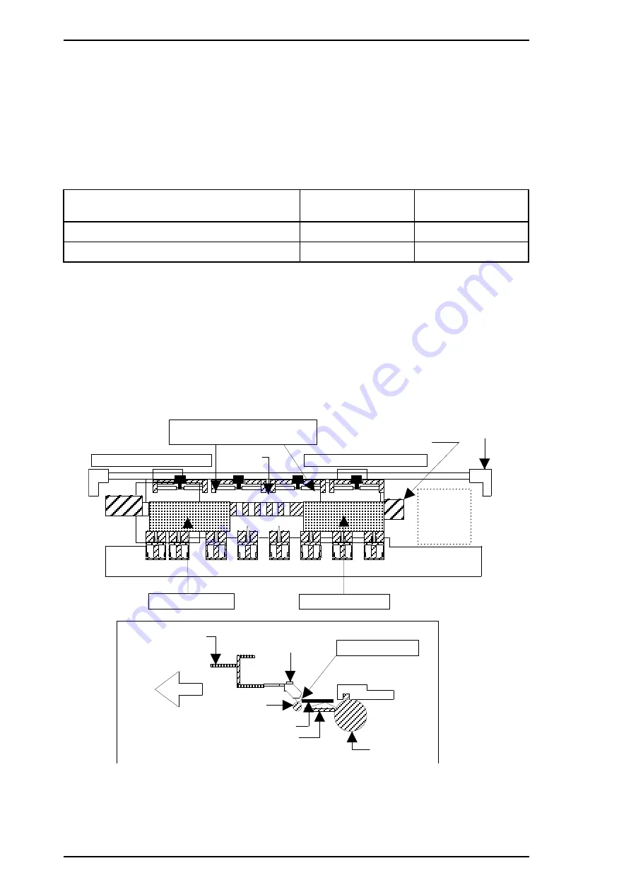
mechanism. Adjust the distance between the printhead nose and the paper surface to 1.1 mm.
1.
Attach a thickness gauge (commercially available) to the left side adjustment position on the
paper guide plate, as shown in the figure below, so that one side hooks the paper feed pinch
roller unit.
2.
Move the carriage unit manually onto the thickness gauge.
Table 4-2. Gap and Adjustment Direction
Gap between Head Nose and Gauge Surface
Left Bushing
Right Bushing
Narrow
CW
CCW
Spread
CCW
CW
3.
Rotate the parallelism adjustment bushing, attached to the left and right ends of the carriage
guide shaft, when the black and color printheads contact the thickness gauge.
4.
After attaching the printheads to the gauge surface, verify that the gap between the carriage
roller and the front frame is less than 0.04 mm. (See Figure 4-16.)
5.
Attach the 1.1 mm thickness gauge to the right side adjustment position on the paper guide
plate, as shown below, so that one side hooks the paper feed pinch roller unit.
Note:
When checking the gap between the carriage roller and the front frame, use the thickness
gauge or the paper guide plate. If the gap is correct the gauge cannot be installed into the
gap. If the gap is incorrect, the gauge can be inserted in the gap.
Attach the thickness gauge
under the PF pinch roller unit.
Left Adjustment Position
Right Adjustment Position
Paper Gui de Plate
Bus hi ng
Pu mp Un it
Eject Fra me
Thickn ess Gaug e
Thi ckness Gauge
Front
Fron t Frame
PF Pinch Roller
Unit
Attachment Poi nt
Tension Ro ller
Thickn ess Gaug e
Pa pe r Gu id e
Pla te n
Figure 4-18. Adjusting the Platen Gap
Adjustments
Stylus Pro XL
4-16
Rev. A
Summary of Contents for Stylus pro 7700m
Page 1: ...EPSON COLOR INKJET PRINTER Stylus Pro SERVICE MANUAL EPSON 4004825 ...
Page 122: ... 5 IC6 Q2 R135 and CN13 are not mounted on the C164 MAIN Board Stylus Pro ...
Page 123: ...Figure A 3 C164 MAIN Board Circuit Diagram 2 Stylus Pro Service Manual Appendix Rev A A 9 ...
Page 124: ...Figure A 4 C137 PSB Board Circuit Diagram Stylus Pro Service Manual Appendix Rev A A 11 ...
Page 125: ...Figure A 5 C137 PSE Board Circuit Diagram Rev A A 12 A 12 Rev A ...
Page 126: ...Figure A 6 C137 PNL Board Circuit Diagram Stylus Pro Service Manual Appendix Rev A A 13 ...
Page 128: ...Figure A 8 C137 PSB PSE Board Component Layout Stylus Pro Service Manual Appendix Rev A A 15 ...
Page 129: ...Figure A 9 C137 PNL Board Component Layout Rev A A 16 A 16 Rev A ...
Page 131: ...Figure A 11 Stylus Color Pro Exploded Diagram 2 Rev A A 18 A 18 Rev A ...
Page 132: ...Figure A 12 Stylus Color Pro Exploded Diagram 3 Stylus Pro Service Manual Appendix Rev A A 19 ...
Page 139: ...EPSON Printed in Japan 95 05 30 A ...


