background image

EPSON Stylus C110/C120/D120

Revision B

DISASSEMBLY/ASSEMBLY     

Disassembling Printer Mechanism

105

4.5.18  PF Roller

†

Part/Unit that should be removed before removing PF Roller

Upper Housing/Lower Housing/Main Board Unit/Left Frame/Panel Unit/Front 
Frame/Right Frame/CR Motor/CR Scale/Hopper/Main Frame Assy./ASF Unit/Ink 
System Unit/Star Wheel Holder Assy./EJ Roller/Front Paper Guide/PF Encoder 
Sensor/PF Scale

†

Removing Procedure

1. Remove the Spur Gear 13.5 from the PF Roller with a flathead precision 

screwdriver or a similar tool.

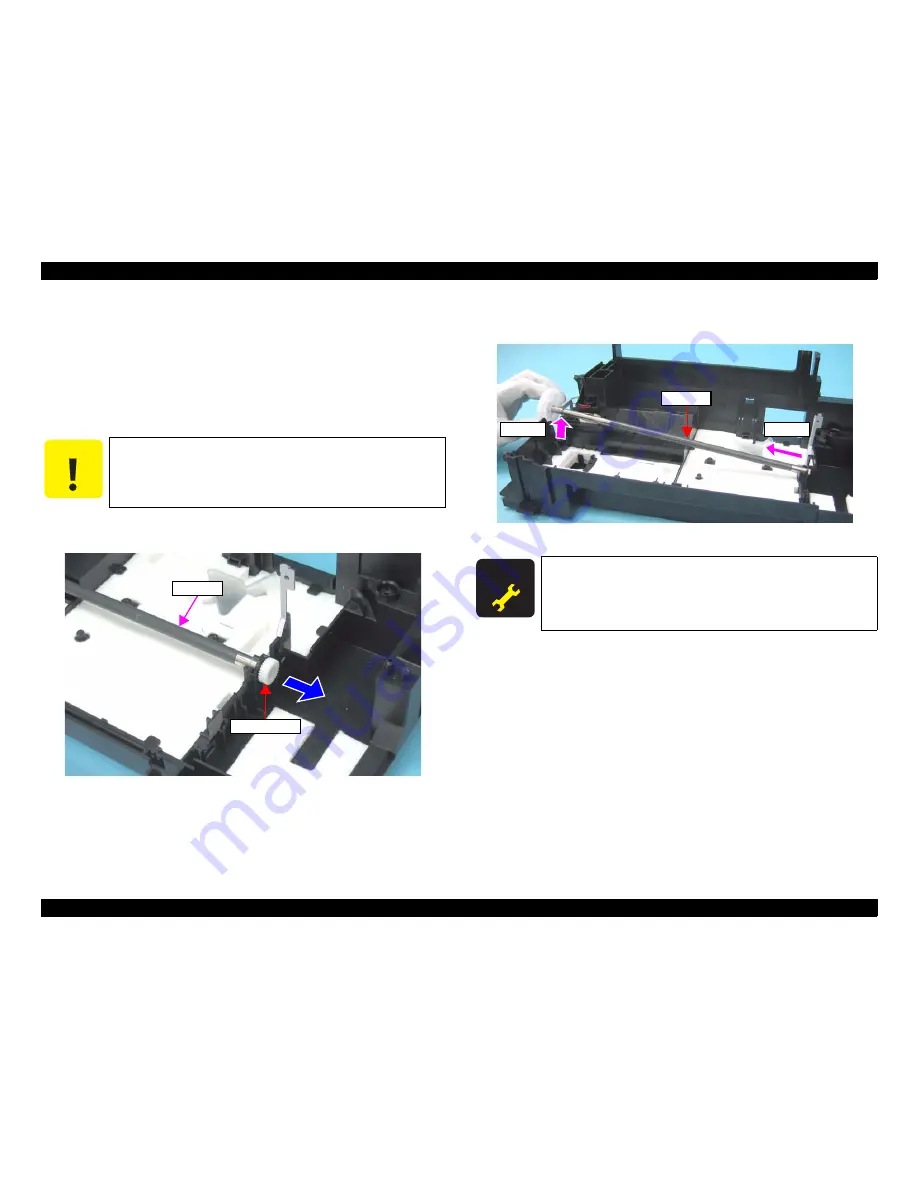
Figure 4-85.  Removing PF Roller (2)

2. Release the PF Roller from the cutout of the Base Frame (Step 2-1), and remove it 

(Step 2-2).

Figure 4-86.  Removing PF Roller (2)

C A U T I O N

When removing the PF Roller, Be cautious not to touch or damage 
the coated surface of the PF Roller.

PF Roller

Spur Gear 13.5

A D J U S T M E N T

R E Q U I R E D

„

After removing/replacing the PF Roller, be sure to perform 
the specified adjustment. See 

Chapter 5 “ ADJUSTMENT” 

(p.107)

„

After replacing the PF Roller, be sure to perform the required 
lubrication. See 

Chapter 6 “ MAINTENANCE” (p.116)

Step 2-1

Step 2-2

PF Roller

Summary of Contents for Stylus C110

Page 1: ...EPSONStylusC110 C120 D120 Color Inkjet Printer SEIJ07 001 SERVICE MANUAL ...

Page 2: ...is manual However should any errors be detected SEIKO EPSON would greatly appreciate being informed of them The above not withstanding SEIKO EPSON CORPORATION can assume no responsibility for any errors in this manual or the consequences thereof EPSON is a registered trademark of SEIKO EPSON CORPORATION General Notice Other product names used herein are for identification purpose only and may be t...

Page 3: ...ON POWER SUPPLY AND OTHER ELECTRONIC COMPONENTS 4 WHEN DISASSEMBLING OR ASSEMBLING A PRODUCT MAKE SURE TO WEAR GLOVES TO AVOID INJURIER FROM METAL PARTS WITH SHARP EDGES WARNING 1 REPAIRS ON EPSON PRODUCT SHOULD BE PERFORMED ONLY BY AN EPSON CERTIFIED REPAIR TECHNICIAN 2 MAKE CERTAIN THAT THE SOURCE VOLTAGES IS THE SAME AS THE RATED VOLTAGE LISTED ON THE SERIAL NUMBER RATING PLATE IF THE EPSON PRO...

Page 4: ... Diagram Parts List Circuit Diagrams Symbols Used in this Manual Various symbols are used throughout this manual either to provide additional information on a specific topic or to warn of possible danger present during a procedure or an action Be aware of all symbols when they are used and always read NOTE CAUTION or WARNING messages Indicates an operating or maintenance procedure practice or cond...

Page 5: ...d 1 2 3 Supported Paper p 12 Note about nominal weight is added Chapter 2 2 1 2 Motors Sensors p 22 Note about a special nozzle of each color on the Printhead is added 2 2 1 Printhead p 23 Note about a special nozzle of each color on the Printhead is added Chapter 4 4 1 2 Tools p 70 The Upper Case Opener is added 4 3 4 Upper Housing Cover Open Sensor p 74 CheckPoint of removing the Right Front Cov...

Page 6: ...ators LEDs 17 1 5 3 Operation Buttons LEDs Functions 17 1 5 4 Errors Remedies 19 Chapter 2 OPERATING PRINCIPLE 2 1 Overview 21 2 1 1 Printer Mechanism 21 2 1 2 Motors Sensors 22 2 2 Printer Mechanism Operating Principles 23 2 2 1 Printhead 23 2 2 2 Carriage Mechanism 25 2 2 3 Paper Loading Paper Feed Mechanism 26 2 2 4 Ink System Mechanism 31 2 2 5 Ink Sequence 34 2 3 Electrical Circuit Operating ...

Page 7: ...5 7 EJ Roller 89 4 5 8 PF Encoder Sensor 90 4 5 9 PF Scale 91 4 5 10 PF Motor 91 4 5 11 CR Motor 93 4 5 12 Main Frame Assy 95 4 5 13 CR Unit 97 4 5 14 Upper Paper Guide 99 4 5 15 ASF Unit 99 4 5 16 Ink System Unit 101 4 5 17 Front Paper Guide 104 4 5 18 PF Roller 105 4 5 19 Waste Ink Pads 106 Chapter 5 ADJUSTMENT 5 1 Adjustment Items and Overview 108 5 1 1 Servicing Adjustment Item List 108 5 1 2 ...

Page 8: ...C H A P T E R 1 PRODUCTDESCRIPTION ...

Page 9: ...higher black white print speed than ever Installs two black ink cartridges as standard Newly developed pigment ink is employed Borderless printing on specified EPSON brand paper is available Control panel Simple design with three buttons and three indicators LED Dimensions Dimensions 435 mm W x 240 mm D x 161 mm H Paper support and stacker are closed Rubber feet are excluded Weight 3 9 kg without ...

Page 10: ...eed rates T B D mm sec at 25 4 mm feed PF interval Programmable in 0 01764 mm 1 1440 inch steps Table 1 2 Print Mode Color Media Print Mode Resolution H x V dpi Dot Size cps Bi d Micro Weave Border less Plain paper Premium Bright White Paper EAI Premium Ink Jet Plain papers others Draft 1 360x180 Eco 400cps ON OFF N A Draft 2 360x180 Eco 400cps ON OFF N A Normal 2 360x360 VSD1 320cps ON OFF N A No...

Page 11: ... Table 1 2 Print Mode Color Media Print Mode Resolution H x V dpi Dot Size cps Bi d Micro Weave Border less Table 1 3 Print Mode Monochrome Media Print Mode Resolution H x V dpi Dot Size cps Bi d Micro Weave Border less Plain paper Premium Bright White Paper EAI Premium Inkjet Plain Paper others Draft 3 360x360 Eco 400cps ON OFF N A Draft 4 360x360 Eco 400cps ON OFF N A Normal 1 360x360 VSD1 320cp...

Page 12: ... 3 x11 7 Y Y Y B5 182 x 257 mm 7 2 x10 1 Y Y A5 148 x 210 mm 5 8 x8 3 Y Y Half Letter 139 7 x 215 9 mm 5 5 x8 5 Y A6 105 x 148 mm 4 2 x5 8 Y Y Y User Defined 89 x 127 329 x 1117 6 mm 3 56 x 5 08 13 16 x44 7 Y Y Y Premium Inkjet Plain Paper A4 210 x 297 mm 8 3 x11 7 0 11 80 g m2 21 lb Y Y Premium Bright White Paper EAI Bright White Inkjet Paper Euro Asia Letter 215 9 x 279 4 mm 8 5 x11 0 11 90 g m2...

Page 13: ... 101 6 x 152 4 mm Y Y Y Y Y Y Premium Presentation Paper Matte EAI Matte Paper Heavyweight Euro Asia Letter 215 9 x 279 4 mm 8 5 x11 0 23 167 g m2 44 lb Y Y A4 210 x 297 mm 8 3 x11 7 Y Y Y Y Y Y 8 x 10 203 2 x 254 mm Y Y Photo Quality Inkjet Paper A4 210 x 297 mm 8 3 x11 7 0 13 102 g m2 27 lb Y Y Envelopes 10 104 8 x 241 3 mm 4 125 x9 5 75 100 g m2 20 27 lb Y Y Y DL 110 x 220 mm Y Y C6 114 x 162 m...

Page 14: ...mm 2 54 mm 2 3 mm 3 67 mm 4 x 6 2 3 mm 3 39 mm Print Area LM RM TM BM BM Cut Sheet Standard Cut Sheet Borderless Paper SIze LM RM TM BM Print Area LM RM Print Area Envelope Paper Size TM Paper Feed Direction Table 1 6 Product No of Ink Cartridges Color EAI Latin Euro CISMEA Asia Black T0681 S T0731H S T0711H S T0711 2S T0731H S T0731 2S T0731H S T0731 2S Cyan T0692 3S T0732 3S T0712 3S T0732 3S T0...

Page 15: ...C120 CLS PRINTER DES EPSON SP Stylus SP C120 MFG EPSON CMD ESCPL2 BDC MDL Stylus SP C120 CLS PRINTER DES EPSON SP Stylus SP C120 Stylus D120 MFG EPSON CMD ESCPL2 BDC D4 D4PX MDL Stylus SP D120 CLS PRINTER DES EPSON SP Stylus SP D120 MFG EPSON CMD ESCPL2 BDC MDL Stylus SP D120 CLS PRINTER DES EPSON SP Stylus SP D120 Stylus C110 MFG EPSON CMD ESCPL2 BDC D4 D4PX MDL Stylus SP C110 CLS PRINTER DES EPS...

Page 16: ...8 Class B CNS14336 EU EN60950 1 EN55022 Class B EN61000 3 2 EN61000 3 3 EN55024 Germany EN60950 1 Russia GOST R IEC60950 1 CISPR 22 Singapore IEC60950 1 Korea K60950 1 KN22 Class B KN61000 4 2 3 4 5 6 11 China GB4943 GB9254 Class B GB17625 1 Argentina IEC60950 1 Australia AS NZS CISPR22 Class B Table 1 10 Environmental Conditions Condition Temperature 1 Humidity 1 2 Shock Vibration Operating 10 to...

Page 17: ...gh speed during power OFF sequence Ink LED orange 1 Lights or flashes when an ink related error occurs 2 Paper LED orange 1 Lights or flashes when an paper related error occurs 2 Power Button Paper Button Ink Button Power LED Paper LED Ink LED Table 1 13 Operation Button Functions Button Function Power Turns the power ON OFF Ink Runs a sequence of ink cartridge replacement The carriage moves to se...

Page 18: ...received 360 dpi VSD1 0 142 mm 1 180 inch 32 dots Note The numbers shown in the figure are nozzle numbers They are not printed on an actual nozzle check pattern Table 1 14 Indicators LEDs Function Printer Status Indicators LEDs Pri ority 1 Power Ink Paper Powering off Flashes at high speed OFF OFF 1 Fatal error OFF Flashes at high speed Flashes at high speed 2 Maintenance request OFF Flashes alter...

Page 19: ...o be replaced Replace the waste ink pads and reset the counter Paper jam A paper jam has occurred Remove the jammed paper and press the Paper button No paper Failed to feed paper Load paper correctly and press the Paper button Multi feed Multiple sheets of paper were fed at the same time Press the Paper button to eject the multiple sheets Ink out The cartridge has run out of ink Replace the ink ca...

Page 20: ...C H A P T E R 2 OPERATINGPRINCIPLE ...

Page 21: ...m paper feed mechanism and ink system As the conventional models Stylus C110 C120 D120 is equipped with two DC motors one is used to drive the paper loading paper feed mechanisms and the pump mechanism that includes the carriage lock mechanism and another one is used to drive the carriage mechanism A paper is fed from the rear ASF unit by means of the LD roller and Retard roller and ejected to the...

Page 22: ...aracteristics Coil resistance 22 7Ω 10 Inductance 15 9mH 1KHz Drive method PWM constant current chopping 3 PF Motor Type DC motor Drive voltage 42VDC 5 DRV IC voltage Characteristics Coil resistance 21 2Ω 10 Inductance 17 2 mH 1kHz Drive method PWM constant current chopping 4 PE Sensor Purpose Detection of paper top and bottom edge for control to set paper at the print start position Type Photo in...

Page 23: ...Electric Element Based on the drive waveform generated on the main board the PZT selected by the nozzle selector IC on the printhead pushes the top of the ink cavity which has ink stored to eject the ink from each nozzle on the nozzle plate Nozzle Plate The plate with nozzle holes on the printhead surface is called Nozzle Plate Filter This filter is located beneath the ink supply needle which supp...

Page 24: ...oltage generated on the main board the PZT selected by the nozzle selector IC pushes the top of the ink cavity By this operation the ink stored in the ink cavity is ejected from nozzles refer to Figure 2 5 p 24 When firing ink drop Figure 2 5 How to Fire Ink Drop 2 2 1 2 Printing Method Stylus C110 C120 D120 offers printing with variable sized dot or printing with economy sized dot Variable dot mo...

Page 25: ...R motor mechanical load the printer runs a CR measurement sequence and stores the measured data into the EEPROM at power on or in an ink cartridge replacement sequence A fatal error occurs if the printer detects that too much load is applied to the CR motor The above control and sequences enable to correct the drive voltage for the CR motor based on the mechanical load and the electrical character...

Page 26: ...he paper top and bottom edges during the loading and feeding operations When the sensor could not detect the top edge of paper during the loading operation the printer causes a paper out error And when the sensor could not detect the bottom edge of paper during feeding operation the printer causes a paper jam error For more details on the errors see Chapter 3 TROUBLESHOOTING p42 Figure 2 7 Paper L...

Page 27: ...e LD roller and paper is fed from the ASF unit The rotation of the two cams on the LD roller feeds paper into the printer Larger cam moves the hopper Smaller cam moves the paper back lever When the first sheet of paper has been fed the second sheet is returned to the standby position by the hopper and the paper back lever which are moved by the cams The following sections explain the paper loading...

Page 28: ... the engagement of the clutch the PF motor pinion gear starts counterclockwise rotation as seen from the left side and the drive force is transmitted to the LD roller shaft via the clutch lock tab and the clutch gear When the LD roller starts to rotate the paper back lever is returned to its standby position and the hopper is released from the cams by being pushed by the spring This causes a sheet...

Page 29: ...ly The paper back lever returns paper to the standby position to prevent multiple sheets of paper from being fed at once When the LD roller and the clutch reach the ASF home position shown in Step1 on the previous page the clutch lever is locked again by the change lever This causes the PF motor drive force not to be transmitted to the paper loading mechanism and to be transmitted only to the pape...

Page 30: ...PF motor drive force is transmitted to the star wheel roller via the EJ roller The figure below shows how the PF motor pinion gear drive force is transmitted to the PF roller EJ roller paper guide roller and the star wheel roller When the PF motor pinion gear starts counterclockwise rotation as seen from the left side the sheet of paper fed from the ASF unit to the PF roller is transported and eje...

Page 31: ... cam of the clutch equipped combination gear See Wiping Mechanism p32 for more explanation about the cap slider and the cam operations Figure 2 15 Carriage Lock Mechanism Table 2 3 Function of Each Mechanism in Ink System Mechanism Function Capping mechanism Covers the printhead with the cap to prevent ink evaporation when the printer is in standby mode or when the printer is off Wiping mechanism ...

Page 32: ...ore the clutch is engaged causing the cam to rotate together with the combination gear The clockwise rotation of the PF motor rotates the cam in clockwise direction to move the wiper upward to clean the head The counterclockwise rotation of the PF motor rotates the cam in counterclockwise direction to move the wiper downward which is out of position for cleaning Groove 2 of the cam is designed so ...

Page 33: ...nk out of the ink cartridges and ink cavity and sends it to the waste ink pad by means of a pressure to the ink tube applied by the pump unit roller The following figure illustrates an overview of the pump unit mechanism operation Note The PF motor rotational direction is as seen from the right side of the printer Figure 2 17 Pump Mechanism Figure 2 18 PF Motor Drive Transmission to Pump Unit Tabl...

Page 34: ...eached or exceeded only CL1 is executed In the case that any of the ink cartridges has almost run out or completely run out of ink the LED flashes or light and the manual cleaning is disabled Timer Cleaning Like the previous printers this printer does not have lithium battery which is used for the backup power source for Timer IC So this printer manages the printer off period or cleaning cycle by ...

Page 35: ...120 employs the simulated oscillating stimulation flyback converter circuit method and it supplies 42VDC to the drive line The application of the output voltage is described below AC voltage input from AC inlet first goes through filter circuit that removes high frequency components and is then converted to DC voltage via the rectifier circuit and the smoothing circuit DC voltage is then lead to t...

Page 36: ...120 which does not have stand alone direct print function Power save mode The main board reduces power consumption by carrying out the followings in the power save mode Partially stops the ASIC clock Brings the motor driver head DAC into sleep standby mode Stops energizing motors Brings the SDRAM into the self refresh mode 2 3 2 1 Major Components on Main Board The table below lists the major comp...

Page 37: ...ock Diagram CPU ASIC IC8 Data Address SDRAM IC2 Flash ROM IC1 Reset IC IC3 EEPROM IC9 CN11 C687 Panel Board USB CN2 CN1 C687 PSB PSE Board Motor driver IC5 CN8 CN9 CN10 CR Motor PF Motor PF Encoder Sensor PE Sensor Cover Open Sensor Head driver IC11 Q3 Q4 CN5 CN6 Printhead CN7 CR Encoder Sensor CR Contact Module Data Address CN3 CN4 ...

Page 38: ...driver IC7 The addresses for the written data are determined by DATA0 DATA9 signals Then the necessary data is selected from the address and appropriate basic drive waveform is generated The generated head drive waveform is transmitted to the nozzle selector IC on the printhead driver board through the transistor Q3 and Q4 and applied to the nozzle PZT specified by nozzle selector IC Nozzle select...

Page 39: ...tor drive voltage to the CR PF motor When no data has been received for 5 minutes the CPU sets the motor driver voltage to 0 and turn the motor driver Off to save power Figure 2 21 Motor Driver Circuit Block Diagram CPU IC8 Motor driver IC5 SCLK1_DCMCU SDATA1_DCMCU SLD1_DCMCU SCLK2_DCMCU SDATA2_DCMCU SLD2_DCMCU ENB1_DCMCU ENB2_DCMCU CLK4M RST_DCMCU C15 B14 C14 A15 A14 B15 D16 A16 D14 C16 OUT1A OUT...

Page 40: ...eps data written to it even after the power off The CPU IC8 reads data from the EEPROM IC4 in the power on sequence and stores data into the EEPROM in the power off sequence EEPROM stores the following information Ink counter Ink consumption in ink cartridges Waste ink pad counter etc Mechanical settings Head ID Bi D adjusted settings USB ID etc EEPROM is connected to the CPU with the four lines E...

Page 41: ...he CR motor based on the signals The carriage unit home position is also detected by the sensor PF Encoder Sensor The sensor consists of the two devices a transmissive photosensor mounted on the main board and a rotary scale attached at the left of the PF Roller Unit Fine black lines are printed on the rotary scale in 1 180 inch of the minimum resolution The photosensor outputs HIGH signal to the ...

Page 42: ...C H A P T E R 3 TROUBLESHOOTING ...

Page 43: ...There is no error in handling of the printer Check the inside of the printer and remove foreign matters if any such as paper clips staples bits of paper paper dust or toner Clean the inside of the printer and the rubber rolls W A R N I N G Be careful to avoid electric shocks when checking the electrical circuit boards C687 MAIN and C687 PSE PSB boards while the power is turned on Touching an FET t...

Page 44: ...een the electric poles varies Visually check the motors for abnormal operation and if it is hard to judge replace the motor Table 3 1 Motor Specification Motor Motor Type Drive Voltage Resistance CR motor DC motor with brash DC 42V 5 22 7Ω 10 PF motor 21 2Ω 10 Table 3 2 Sensor check point Sensor name Check point Signal level Switch mode Open Cover Sensor CN4 Pin 1 and 2 Less than 0 4V Off Case ope...

Page 45: ...y This error occurs when about 90 percent of ink consumed Note Even if this error is indicated on the STM3 you can continue printing until a Replace Ink Cartridge error appears However the Head Cleaning may not be performed during the ink low status This error occurs when multiple sheets of paper are fed simultaneously The error condition is detected when paper length longer than its preset length...

Page 46: ...hen data from CSIC cannot be read normally or when data cannot be written to CSIC This error occurs when any one of the followings is detected An unsupported ink cartridge has been installed An ink cartridge with a different destination has been installed This error occurs when the PE Sensor failed to detect the paper bottom edge during paper feeding sequence Reference Page Table 3 7 Check point f...

Page 47: ...Brink 3 Brink 4 Status monitor 3 message Fault Occurrence Cause This error occurs when the Waste Ink Counter exceeds the preset counter value This error occurs when a mechanical error is detected CR error PF error etc This error occurs when the Cover Open sensor detects the printer cover is opened Reference Page Table 3 5 Check point for the Maintenance request according to each phenomenon on page...

Page 48: ...tor Cable to CN8 on the Main Board 2 Check if the CR Motor Connector Cable is not damaged 2 Replace the CR Motor with a new one 3 Check if the CR Motor operates 3 Replace the CR Motor with a new one When turning on the power the PF Motor does not operate at all PF Motor 1 Check if the PF Motor Connector Cable is connected to CN9 on the Main Board 1 Connect the PF Motor Connector Cable to CN9 on th...

Page 49: ... 3 Check if the PF Motor operates 3 Replace the PF Motor with a new one ASF Unit 1 Check if the Compression Spring 2 36 does not come off in the Change Lever 1 Replace the ASF Unit with a new one The Carriage Unit collides with the Upper Paper Guide Unit when power is turned on Upper Paper Guide Unit 1 Check if the Paper Guide Upper Unit is correctly assembled 1 Reassemble the Upper Paper Guide Un...

Page 50: ...s not damaged or contaminated 2 Replace the CR Scale with a new one or clean it completely CR Encoder Board 1 Check if the Encoder FFC is connected to the CR Encoder Board 1 Connect the Encoder FFC to the CR Encoder Board 2 Check if the Encoder FFC is not damaged 2 Replace the Encoder FFC with a new one 3 Check if the CR Encoder Board is not damaged 3 Replace the CR Encoder Board with a new one Ta...

Page 51: ...eding sequence failed to feed the paper but a paper ejection sequence is performed ASF Unit 1 Check if the PE Sensor Connector Cable is connected to CN3 on the Main Board 1 Connect the PE Sensor Connector Cable to CN3 on the Main Board 2 Check if the PE Sensor Connector Cable is not damaged 2 Replace the ASF Unit with a new one 3 Check if the PE Sensor is not damaged 3 Replace the ASF Unit with a ...

Page 52: ...t the Cover Open Sensor Connector Cable to CN4 on the Main Board 2 Check if the Cover Open Sensor Connector Cable is not damaged 2 Replace the Upper Housing with a new one 3 Check if the Cover Open Sensor is not damaged 3 Replace the Upper Housing with a new one Table 3 5 Check point for the Maintenance request according to each phenomenon Occurrence timing CR position Detailed phenomenon Defectiv...

Page 53: ...Unit 1 Check if the ASF Unit is properly installed 1 Install the ASF Unit properly 2 Check if the Paper Back Lever operates correctly in the paper loading sequence 2 Set the Extension Spring 6 45 between the ASF Frame and the Paper Back Lever Paper is being resent during paper feeding operation ASF Unit 1 Check if the Extension Spring Retard operates correctly in the paper loading sequence 1 Set t...

Page 54: ...lders correctly EJ Roller Unit 1 Check if the EJ Roller Unit is correctly assembled 1 Reassemble the EJ Roller Unit correctly 2 Check if the Spur Gear 51 5 is not damaged 2 Replace the EJ Roller Unit with a new one In case that the paper jam error occurs in each operation the jammed paper contacts the nozzle surface of the Printhead and the Printhead may be damaged Table 3 6 Check point for paper ...

Page 55: ...assembled 1 Reassemble the Upper Paper Guide Unit to the Main Frame correctly In case that the paper jam error occurs in each operation the jammed paper contacts the nozzle surface of the Printhead and the Printhead may be damaged Table 3 6 Check point for paper jam error according to each phenomenon Occurrence timing CR position Detailed phenomenon Defective unit part name Check point Remedy Uppe...

Page 56: ...Ink Cartridge 1 Check if Ink Cartridge is properly installed 1 Install the Ink Cartridge properly 2 Check if the Memory Chip is not disconnected or not chipped 2 Replace the Ink Cartridge with a new one CSIC Board 1 Check if the Head FFC is connected to connector on the CSIC Board 1 Connect the Head FFC to connector on the CSIC Board 2 Check if the CSIC Board is not damaged 2 Replace the CSIC Boar...

Page 57: ...paper from the Printer driver The micro pearl on the LD Roller surface is removed To remove severe smear staple a cloth moistened with alcohol to a post card and clean the roller in the same manner If the problem is not solved replace the ASF unit with new one The Hopper does not operate during the paper loading sequence although the LD Roller rotates to load paper from the ASF Unit Hopper 1 Check...

Page 58: ...le the positioning hole of the Clutch on the guide pin of the LD Roller Shaft 3 Check if the Clutch tooth is not damaged 3 Replace the ASF Unit with a new one 4 Check if the Clutch is not damaged 4 Replace the ASF Unit with a new one 5 Check if the Compression Spring 2 36 does not come off in the Change Lever 5 Replace the ASF Unit with a new one Table 3 8 Check point for paper out error according...

Page 59: ...ing according to each phenomenon Occurrence timing CR position Detailed phenomenon Defective unit part name Check point Remedy Operation Head Cleaning is not carried out Ink Cartridge 1 Check if the ink is remaining in the Ink Cartridge 1 Replace the Ink Cartridge with a new one 2 Check if the Ink Cartridge can be used by installing it to other printer 2 Replace the Ink Cartridge with a new one Ta...

Page 60: ...e printed the paper was ejected but an error is displayed ASF Unit 1 Check if the Extension Spring Retard operates correctly in the paper loading sequence 1 Set the Extension Spring Retard between the Retard Roller Unit and the ASF Frame 2 Check if the Paper Back Lever operates correctly in the paper loading sequence 2 Set the Extension Spring 6 45 between the ASF Frame and the Paper Back Lever Ex...

Page 61: ...he Panel Board 2 Check if the Panel FFC is not damaged 2 Replace the Panel FFC with new one 3 Check if the Panel Board is not damaged 3 Replace the Panel Board with new one Power on Anywhere When turning on the power the printer does not operate at all PS Board Unit 1 Check if the PS Board Connector Cable is connected to CN1 on the Main Board 1 Connect the PS Board Connector Cable to CN1 on the Ma...

Page 62: ...onnect the USB Cable to the printer and the PC Main Board Unit 1 Check if an correct model name is stored into the address of the EEPROM on the Main Board 1 Use the Adjustment Program to write the correct value to the EEPROM address 2 Check if the Panel FFC is connected to CN11 on the Main Board 2 Connect the Panel FFC to CN11 on the Main Board Table 3 11 Check point for communication error accord...

Page 63: ...iled phenomenon Defective unit part name Check point Remedy Operation The LEDs and STM3 are not indicating error conditions But multiple sheets of paper are always loaded from the ASF Unit ASF Unit 1 Check if the Extension Spring Retard operates correctly in the paper loading sequence 1 Set the Extension Spring Retard between the Retard Roller Unit and the ASF Frame 2 Check if the Paper Back Lever...

Page 64: ...etailed phenomenon Defective unit part name Check point Remedy Dot missing and mixed colors Ink is scarcely ejected to the Cap from the Printhead Ink System Unit Cap Unit 1 Check if there is not any foreign material damage around the seal rubber part on the Cap Unit 1 Remove the foreign material around the seal rubber parts carefully 2 Check if the Compression Spring 1 47 is correctly mounted on t...

Page 65: ...ks like uneven printing Note If the problem is not solved replace the CR Motor with a new one Adjustment 1 For printing in the Bi D mode check if Bi D Adjustment has been performed properly 1 Perform Bi D Adjustment to correct print start position in bi directional printing Refer to Chapter 5 ADJUSTMENT p 107 Printhead 1 Check if the Nozzle Check Pattern is printed properly 2 Perform Head Cleaning...

Page 66: ...lean the surface of the PF Roller Unit carefully with the soft cloth 2 Check if the PF Roller Unit is not damaged 2 Replace the PF Roller Unit with a new one The Star wheel mark against the CR movement direction Star Wheel Holder Assy 1 Check if the Star Wheel Holder does not come off 1 Reassemble the Star Wheel Holder correctly 2 Check if the surface of the Star Wheel Holder Assy is flat 2 Replac...

Page 67: ...or If the problem is not solved replace the ASF Unit with a new one Ink stain of paper Ink stain occurs at the back top end or bottom end of the print paper Front Paper Guide 1 Check if the Front Paper Guide Unit is free from ink stain 1 Clean the Front Paper Guide Unit with a soft cloth 2 Check if heaps of ink are not formed on Porous Pad Front Paper Guide 2 Replace the Front Paper Guide Assy wit...

Page 68: ... the Printhead Cover carefully with a soft cloth Upper Paper Guide Unit 1 Check if the Upper Paper Guide Unit is free from ink stain 1 Clean the Upper Paper Guide Unit with a soft cloth Star Wheel Holder Assy 1 Check if the Star Wheels is free from ink stain 1 Clean the Star Wheels with a soft cloth Table 3 14 Check point for the poor printing quality Print Quality State Detailed phenomenon Defect...

Page 69: ...C H A P T E R 4 DISASSEMBLY ASSEMBLY ...

Page 70: ...ctly follow the instructions in this manual Always wear gloves for disassembly and reassembly to protect your eyes from ink If any ink gets in your eyes wash your eyes with clean water and consult a doctor immediately Always wear gloves for disassembly and reassembly to avoid injury from sharp metal edges To protect sensitive microprocessors and circuitry use static discharge equipment such as ant...

Page 71: ...eding Mechanism Is paper advanced smoothly OK NG No paper jamming OK NG No paper skew OK NG No multiple feeding OK NG No abnormal noise OK NG Is the paper path free of any obstructions OK NG Is the PF Motor at correct temperature OK NG ON line Test ON line Test Is the operation normal OK NG Adjustment Specified Adjustment Are all the adjustments done correctly OK NG Lubrication Specified Lubricati...

Page 72: ...anel Unit p79 4 4 3 Power Supply Unit p81 4 5 4 Hopper p86 4 5 14 Upper Paper Guide p99 4 5 1 Removing Printer Mechanism Lower Housing p82 4 4 2 Panel Unit p79 4 5 11 CR Motor p93 4 5 4 Hopper p86 4 5 16 Ink System Unit p101 4 5 6 Star Wheel Holder Assy p88 4 5 9 PF Scale p91 4 5 18 PF Roller p105 4 4 1 Main Board Unit Left Frame p76 4 5 15 ASF Unit p99 4 5 6 Star Wheel Holder Assy p88 4 5 7 EJ Ro...

Page 73: ...ure the Paper Support Assy and remove it from the Upper Housing Figure 4 2 Removing Paper Support Assy 4 3 2 Stacker Assy Part Unit that should be removed before removing Stacker Assy None Removal Procedure 1 Open the Stacker Assy 2 Release the Stacker Assy while pressing in the hook x1 on the right with a flathead precision screwdriver or a similar tool and then remove it Figure 4 3 Removing Stac...

Page 74: ...over Open Sensor Part Unit that should be removed before removing Upper Housing Cover Open Sensor None Removal Procedure 1 Open the Paper Support Assy 2 Open the Stacker Assy 3 Remove the Right Front Cover Figure 4 5 Removing Right Front Cover Cover Printer Guide pin C H E C K P O I N T Stress whitening easily occurs in the hooks of the Right Front Cover Be careful not to apply too much force on t...

Page 75: ...remove the Upper Housing Figure 4 7 Removing Upper Housing 2 Upper Housing C B P 3x10 F Zn 3C 6 1kgfcm C B P 3x12 F Zn 3C 6 1kgfcm 4 3 1 2 Printer Rear Tighten the screws in the order given in Figure 4 6 If the acetate tape that secures the cable of the Cover Open Sensor comes off attach it correctly referring to the figure below Figure 4 8 Acetate Tape Position Connector of Cover Open Sensor Cove...

Page 76: ...1 Disconnect the following connectors x4 and FFCs x5 from the Main Board Figure 4 9 Connector Layout of Main Board C A U T I O N Be careful not to bend or damage the Panel Unit FFC when removing it CN No Cable CN No Cable CN1 Power Supply Unit cable CN8 CR Motor cable CN3 PE Sensor cable CN9 PF Motor cable CN5 Head FFC CN10 PF Encoder FFC CN6 Head FFC CN11 Panel Unit FFC CN7 Head FFC CN8 CN9 CN3 C...

Page 77: ... Left frame Figure 4 11 Removing Main Board Unit Left Frame 2 4 Peel off the Panel Unit FFC from both the Main Board Unit and the Left Frame and remove them together Figure 4 12 Removing Main Board Unit Left Frame 3 5 Remove the screw x1 that secures the Left Frame and remove the Main Board Unit Figure 4 13 Removing Main Board Unit Left Frame 4 Head FFC Acetate Tape Hook C B P 3x6 F Zn 3C 6 1kgfcm...

Page 78: ...nel Unit FFC Double sided tape position Tab Slot When routing the Head FFC on the Left Frame secure the Head FFC with an acetate tape on the specified position as shown in the figure below Figure 4 16 Acetate Tape Position Be cautious of the following points when connecting the cables to the Main Board 1 Do not let the cables and FFCs over the USB interface 2 Route the CR Motor cable and the PF Mo...

Page 79: ...onnect the FFC x1 from the connector of the Panel Unit 2 Release the rib x1 of the Panel Unit from the cutout x1 of the Front Frame and remove the Panel Unit Figure 4 18 Removing Panel Unit 3 Remove the screws x2 that secure the Panel Board and the Panel Shield Plate and remove them together Figure 4 19 Removing Panel Board Panel Unit Connector of the Panel Unit FFC Rib and Cutout Marking off Line...

Page 80: ...tioning holes x2 of the Light Guide Tube as shown in Figure 4 20 Insert the guide pins x2 of the Panel Housing into the positioning holes x2 of the Main Board as shown in Figure 4 19 When routing the Panel Unit FFC tape the FFC to the Panel Unit with a double sided tape Both edge of the Panel Unit FFC must be aligned with the marking off line as shown in Figure 4 18 Panel Housing Light Guide Tube ...

Page 81: ...ng Power Supply Unit C B P 3x10 F Zn 3C 6 1kgfcm Power Supply Unit 1 2 When installing the Power Supply Unit make sure to check the following points Insert the tabs x2 of the Power Supply Unit into the holes on the Base Frame Figure 4 22 Installing the Power Supply Unit Tighten the screws in the order given in Figure 4 21 Put the ferrite core attached to the Power Supply Unit cable into the cutout...

Page 82: ...edure 1 Remove the screws x4 that secure the Printer Mechanism to the Lower Housing and remove it Figure 4 25 Removing Printer Mechanism C A U T I O N When lifting the Printer Mechanism be sure to hold the positions specified in the figure below to prevent the Main Frame from becoming deformed Figure 4 24 Printer Mechanism Handling Precaution Right Hand Position Left Hand Position Tighten the scre...

Page 83: ...ver and remove all the ink cartridges from the CR Unit 3 Release the hook x1 of the Head Cable Cover with a flathead precision screwdriver and remove the Head Cable Cover while sliding it downward in the direction of the arrow Figure 4 27 Removing Printhead 1 4 Disconnect the Head FFC x1 that is connected to the CSIC Board 5 Release the tabs x2 that secure the Holder Board Assy using a needle or a...

Page 84: ...he Printhead Figure 4 30 Removing Printhead 4 C A U T I O N Do not touch or damage the nozzles or the ink supply needles of the Printhead C B S 2 5x8 F Zn 3C 3 1kgfcm 1 2 3 Printhead Head FFC Tighten the screws in the order given in Figure 4 29 Insert the Holder Board Assy vertically into the CR Unit so as not to put the assy on the rib of the Printhead A D J U S T M E N T R E Q U I R E D After re...

Page 85: ... in the figure and remove the scale from the Main Frame Figure 4 32 Removing CR Scale 2 C A U T I O N Pay attention to the following instructions Do not touch the CR Scale with bare hands Do not damage the CR Scale Do not stretch Extension Spring 3 289 too much CR Scale CR Scale Hook Slit of CR Encoder Sensor When installing the CR Scale pay attention to the following instructions Chipped part of ...

Page 86: ...wel B of the Hopper and remove the Hopper together with the Compression Spring 1 94 Figure 4 33 Removing Hopper Dowel B Dowel A Hopper Compression Spring1 94 When installing the Hopper be sure to engage the rib of the Hopper with the guide groove of the Base Frame Figure 4 34 Installing Hopper A D J U S T M E N T R E Q U I R E D After removing replacing the Hopper be sure to perform the specified ...

Page 87: ...C from the hooks x3 of the Front Frame 3 Remove the Grounding Spring from the Front Frame Figure 4 35 Removing Front Frame Right Frame 1 4 Remove the screw x1 that secure the Front Frame and the Right Frame together 5 Release the dowel x1 and the hook x1 that secure the Right Frame and remove it Figure 4 36 Removing Front Frame Right Frame 2 6 Release the hook x1 and remove the Front Frame Figure ...

Page 88: ...e be sure to attach an acetate tape referring to the figure below Figure 4 38 Acetate Tape Position When installing the Front Frame pay attention to the following instructions As shown in Figure 4 37 be sure to secure the Front Frame with the hook x1 and the cutouts x2 As shown in Figure 4 36 secure the Front Frame and Right Frame together with the screw Place the Right Frame on top of the Front F...

Page 89: ...s removed make sure to attach a new one Spur Gear 51 5 EJ Roller Tab EJ Roller When installing the EJ Roller pay attention to the following instructions Make sure that the rubber part of the EJ Roller does not contact with the hook of the Front Paper Guide Be cautious not to touch the rubber part of the EJ Roller Be sure to align the rib x1 of the Front Paper Guide with the slit on the EJ Roller F...

Page 90: ...ate tape x1 from the PF Encoder Sensor 2 Release the PF Encoder FFC from the connector x1 of the PF Encoder Sensor 3 Remove the screw x1 that secures the PF Encoder Sensor and remove it Figure 4 45 Removing PF Encoder Sensor Acetate Tape PF Encoder FFC C B P 2 5x8 F Zn 3C 4 1kgfcm PF Encoder Sensor When installing the PF Encoder Sensor be sure to attach the acetate tape x1 referring to the figure ...

Page 91: ...r Housing Lower Housing Main Board Unit Left Frame Panel Unit PF Encoder Sensor PF Scale Removal Procedure 1 Release the PF Motor connector cable from the notches x2 of the Base Frame Figure 4 48 Removing PF Motor 1 2 Remove the Grounding Spring from the PF Motor 3 Remove the screws x3 that secure the PF Motor and remove it Figure 4 49 Removing PF Motor 2 C A U T I O N Pay attention to the followi...

Page 92: ...in Figure 4 49 Follow the steps below to install the Grounding Spring 1 Attach the larger U shaped end of the Grounding Spring to the PF Roller Figure 4 51 Attaching Grounding Spring 1 PF Motor Connector Cable 71mm or more Grounding Spring PF Roller 2 Pass the Grounding Spring along the inner side of the hook of the Main Frame 3 Ground the smaller U shaped end of the Grounding Spring with the unde...

Page 93: ... of the Timing Belt by pressing the Driven Pulley Holder in the direction of the arrow as shown in the figure and release the Timing Belt from the pinion gear of the CR Motor 4 Remove the screws x2 that secure the CR Motor and remove it Figure 4 54 Removing CR Motor 2 C A U T I O N Be careful not to damage the CR Motor cable when releasing the cable from the hooks of the Main Frame CR Motor Connec...

Page 94: ... groove on it faces downward Figure 4 55 Installing CR Motor Tighten the screws in the order given in Figure 4 54 Make sure that there is no gap between the CR Motor and the Main Frame A D J U S T M E N T R E Q U I R E D After replacing the CR Motor be sure to perform the required adjustment See Chapter 5 ADJUSTMENT p 107 CR Motor Groove ...

Page 95: ... Pulley Holder Figure 4 56 Removing Extension Spring and Driven Pulley Holder 3 Move the CR Unit to left side of the printer 4 Remove the screw x1 that secures the LD Shaft Holder 5 Move the LD Shaft Holder in the direction of the arrow while holding down its tab with a flathead precision screwdriver and remove the LD Shaft Holder Figure 4 57 Removing LD Shaft Holder 6 Remove the Extension Springs...

Page 96: ...igure 4 59 Precaution on Handling Main Frame Assy 4 LD Roller Shaft 3 2 5 C B S 3x6 F Zn 3C 8 1kgfcm Holding Position C B P 3x8 F Zn 3C 6 1kgfcm Main Frame Assy 1 6 When installing the Main Frame Assy pay attention to the following instructions 1 Put the right part of the Upper Paper Guide indicated in the figure below under the LD Roller Shaft 2 Align the hook x1 of the Frame Support with the pos...

Page 97: ... 60 Follow the steps below to install the Extension Spring 10 99 to the Upper Paper Guide 1 Attach the one end of the Extension Spring 10 99 to the hook of the Upper Paper Guide 2 Attach the another end of the Extension Spring 10 99 to the hook of the Main Frame with a longnose plier Figure 4 62 Installing Extension Spring 10 99 Be sure to install the Grounding Spring referring to Figure 4 49 and ...

Page 98: ... below Figure 4 65 Attaching Ink Position Label Timing Belt Groove CR Unit Ink Position Label Carriage Cover Attach the label here The chipped corner must come to the upper left Put the part of the Timing Belt that has serrated surface on its both sides into the groove of the CR Unit Figure 4 66 Installing Timing Belt After removing replacing the CR Unit be sure to perform the specified adjustment...

Page 99: ...g ASF Unit Upper Housing Lower Housing Main Board Unit Left Frame Panel Unit Front Frame Right Frame CR Motor CR Scale Hopper Main Frame Assy Removal Procedure 1 Release the PE Sensor cable from the notches x6 of the Base Frame and pull out the cable out of the hole x1 Figure 4 68 Releasing PE Sensor Cable After removing replacing the Upper Paper Guide be sure to perform the specified adjustment S...

Page 100: ...lign the guide pins x2 of the Base Frame with the positioning holes x2 of the ASF Unit shown in the Figure 4 70 When routing the PE Sensor cable pay attention to the following instructions Route the cable in the order given in Figure 4 68 Make sure to face the blue line of the cable toward the Base Frame Figure 4 72 Routing PE Sensor Cable Check if there is no slack in the cable A D J U S T M E N ...

Page 101: ...te Ink Tube 3 Remove the screw that secures the Ink System Unit x1 4 Slide the Ink System Unit in the direction of the arrow while releasing its hook with flathead precision screwdriver and remove the Ink System Unit Figure 4 75 Removing Ink System Unit C A U T I O N When disassembling assembling the Ink System Unit pay attention to the following instructions Be cautious not to get injured with th...

Page 102: ...ge Lock Lever into the hole x1 of the Ink System Unit Figure 4 76 Installing Carriage Lock Lever Carriage Lock Lever Extension Spring 0 8 Ink System Unit Dowel and Hole When installing the Ink System Unit pay attention to the following instructions Align the dowels x3 of the Ink System Unit with the positioning holes x3 of the Base Frame Figure 4 77 Installing Ink Stem Unit 1 Align the ribs x2 of ...

Page 103: ...of the Base Frame so that the red line of the Waste Ink Tube faces to the Ink System Unit side Figure 4 79 Routing Waste Ink Tube Referring to the figure below attach the Tube Stopper to the Waste Ink Tube and insert them into the Waste Ink Cover Figure 4 80 Installing Waste Ink Tube Waste Ink Tube Groove Tube Stopper Waste Ink Tube 30 1mm ...

Page 104: ... not to damage the rib on the upper surface of the Front Paper Guide Figure 4 81 Rib of the Front Paper Guide Rib Front Paper Guide C B P 3x10 F Zn 3C 6 1kgfcm 1 2 When installing the Front Paper Guide be cautious not to damage the PF Roller Make sure that the tip of the PGF Pad is put in the correct position as shown in the figure below It should not get caught between the Front Paper Guide and t...

Page 105: ... from the PF Roller with a flathead precision screwdriver or a similar tool Figure 4 85 Removing PF Roller 2 2 Release the PF Roller from the cutout of the Base Frame Step 2 1 and remove it Step 2 2 Figure 4 86 Removing PF Roller 2 C A U T I O N When removing the PF Roller Be cautious not to touch or damage the coated surface of the PF Roller PF Roller Spur Gear 13 5 A D J U S T M E N T R E Q U I ...

Page 106: ... Cover and the Diffusion Sheet Figure 4 88 Removing Waste Ink Cover and Diffusion Sheet A B C A Waste Ink Pads x2 B Waste Ink Pads x3 C Waste Ink Pads x1 Waste Ink Cover Diffusion Sheet Guide Pin and Positioning Hole When installing the Diffusion Sheet Waste Ink Cover and the Waste Ink Pads x3 on section B attach them in the order given in the figure below Figure 4 89 Installing Waste Ink Pads Whe...

Page 107: ...C H A P T E R 5 ADJUSTMENT ...

Page 108: ...the ID printed on the Head QR code label attached on the printhead The correction values are automatically written to the main board Adjustment Program TOP margin adjustment This corrects top margin of printout A top margin adjustment pattern is printed Examine the lines printed near the top edge of the printout and enter the value for the line that is exactly 3 mm away from the top edge Adjustmen...

Page 109: ...justment Items Adjustment Item Purpose Method Outline Tool Table 5 2 Maintenance Items Maintenance Item Purpose Method Outline Tool Waste ink pad counter The printer causes a maintenance error when the waste ink pad counter reaches its maximum Use this to reset the counter after replacing the Waste Ink Pad If you find the counter is close to the maximum during servicing carry out the pad replaceme...

Page 110: ...d ID input Top margin adjustment First dot position adjustment Head angular adjustment Bi D adjustment Initialize PF deterioration offset Disenable PF deterioration offset CR motor heat protection control PF motor heat protection control PF adjustment PF band adjustment Main board unit Remove Replace Read OK O Replace Read NG O O O Replace the pad O O O O O O Input max value 10000 O O O O Printhea...

Page 111: ...w main board for replacing the Printer Mechanism the Initial setting must have been made to the main board Table 5 4 Required Adjustment List Priority 1 2 3 4 5 6 7 8 9 10 11 12 13 14 15 EEPROM data copy Initial setting USB ID input Waste ink pad counter Ink charge Head ID input Top margin adjustment First dot position adjustment Head angular adjustment Bi D adjustment Initialize PF deterioration ...

Page 112: ...ern is printed Figure 5 1 Top Margin Adjustment Printout Pattern How to Judge Measure the length from the top edge of the paper to the printed line Enter the value for the line that is exactly 3 mm away from the top edge 5 2 2 First Dot Position Adjustment The following pattern is printed Figure 5 2 Fist Dot Position Adjustment Printout Pattern How to judge Measure the length from the left edge of...

Page 113: ...t lines it indicates that the printhead is not installed correctly Reassemble the printhead and carry out this adjustment again 5 2 4 Bi D Adjustment The following pattern is printed for each of the five print mode five dot size modes Figure 5 4 Bi D Adjustment Printout Pattern How to Judge Examine the printout patterns for each of the five modes and enter the value for the pattern with no gap and...

Page 114: ...tom margin area The following pattern is printed Figure 5 6 PF bottom margin area Adjustment Printout Pattern How to Judge Examine the printout patterns and enter the value for the pattern with no overlap and gap between the upper and lower ones Additional Information When overlap and gap are observed in the all patterns enter the value for the best one and print the adjustment pattern again C H E...

Page 115: ...djustment Printout Pattern How to Judge Examine the printout patterns and enter the value for the pattern with no overlap and gap between the two rectangles Additional Information When overlap and gap are observed in the all patterns enter the value for the best one and print the adjustment pattern again C H E C K P O I N T Example for judgement 1 0 1 NG NG OK ...

Page 116: ...C H A P T E R 6 MAINTENANCE ...

Page 117: ... the ink consumption amount for manual cleaning varies depending on each mode 6 1 2 2 Maintenance request error Ink is used for the Printhead cleaning or cap flushing operation as well as the printing operation When the ink is used for the Printhead cleaning or flushing operation the ink is drained via the pump to the Waste ink pads the amount of the waste ink is stored as the waste ink counter in...

Page 118: ...d assembled If necessary Refer to the following figures for the lubrication points Figure 6 1 Lubrication on Driven Pulley C A U T I O N Never use oil or grease other than those specified in this manual Use of different types of oil or grease may damage the component or give bad influence on the printer function Never apply larger amount of grease than specified in this manual Type Name EPSON Code...

Page 119: ...nt Remarks Use a brush to apply G 74 Front Paper Guide Lubrication Points Lubrication Point Contact areas x 2 with the PF Roller Lubrication Type G 71 Lubrication Amount φ 1 mm x 4 mm φ 1 mm x 6 mm Remarks Use an injector to apply G 71 Front Paper Guide 1 2 Lubrication Point Bearing of the PF Roller Lubrication Type G 71 Lubrication Amount φ 1 mm x around shaft x 3 Remarks Use an injector to apply...

Page 120: ...71 Lubrication Amount φ 1 mm x 4 mm Remarks Use an injector to apply G 71 Lubrication must be performed only after installing the PF Roller Grounding Spring PF Roller Grounding Spring PF Roller Lubrication Point Cam A and Cam B of the LD Roller shaft Lubrication Type G 71 Lubrication Amount φ 1 mm x around each cam Remarks Use an injector to apply G 71 Rub off excess G 71 with a cotton bud if nece...

Page 121: ...n the lubrication points with a cloth beforehand Main Frame Right Side View Inner surface of the Main Frame Lubrication Point x 2 Main Frame 7 mm 2 8 mm A B Right Side View Outer surface of the Main Frame Lubrication Point x 2 3 5 mm 3 3 mm C D Main Frame Lubrication Point Along the contact area between the back of the Main Frame and the CR Unit Lubrication Type G 71 Lubrication Amount φ 2 mm x 27...

Page 122: ...C H A P T E R 7 APPENDIX ...

Page 123: ...Parts List This manual does not provide exploded diagrams or parts list For the information see SPI Service Parts Information 7 2 Electrical Circuits The electric circuit diagrams below are shown at the following pages Main Board C687 MAIN Panel Board C687 PNL Power Board C687 PSB Power Board C687 PSE ...

Page 124: ...Model PX V780 Stylus C110 C120 D120 Board C687 MAIN Rev C Sheet 1 1 ...

Page 125: ...Model PX V780 Stylus C110 C120 D120 Board C687 PNL Rev A Sheet 1 1 ...

Page 126: ...Model PX V780 Stylus C110 C120 D120 Board C687 PSB Rev B Sheet 1 1 ...

Page 127: ...Model PX V780 Stylus C110 C120 D120 Board C687 PSE Rev B Sheet 1 1 ...

Reviews: