5. FUNCTIONAL DESCRIPTION
S1F76640 Technical Manual (Rev.1.5)
EPSON
7
%
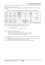
Temperature gradient selection circuit
As shown in Table 5.1, the S1F76640 provides three types of temperature gradients suitable for LCD driving to
V
REG
output.
Table 5.1 Correspondence between Temperature Gradients and V
REG
Output ON/OFF
XP
OFF
Note 1)
TC2
Note 1)
TC1
Note 1)
Temperature
gradient CT
Note 2)
V
REG
output
CR
oscillation
circuit
Remarks
1(V
DD
) L(V
SS
) L(V
SS
) -0.40%/
°
C ON ON
-
1(V
DD
) L(V
SS
) H(V
OUT
) -0.30%/
°
C ON ON
-
1(V
DD
) H(V
OUT
) L(V
SS
) -0.50%/
°
C ON ON
-
1(V
DD
) H(V
OUT
) H(V
OUT
) -0.50%/
°
C ON OFF
Serial connection
Note 4)
0(V
SS
) L(V
SS
) L(V
SS
)
-
OFF(Hi-Z) Note 3)
OFF
-
0(V
SS
) L(V
SS
) H(V
OUT
)
-
OFF(Hi-Z) Note 3)
OFF
-
0(V
SS
) H(V
OUT
) L(V
SS
)
-
OFF(Hi-Z) Note 3)
OFF
-
0(V
SS
) H(V
OUT
) H(V
OUT
)
-
OFF(Hi-Z)
ON
Boosting only Note 5)
Note 1: The high voltage is different between the XP
OFF
, TC2, and TC1 pins.
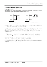
Note 2: The temperature gradient CT is defined in the following formula:
V
REG
(50
°
C) - V
REG
(0
°
C) 1
CT= × ×100 (%/
°
C)
50
°
C - 0
°
C V
REG
(25
°
C)
Example: When CT- = -0.3%/
°
C is selected;
if V
REG
output at Ta = 25
°
C is V
REG
(25
°
C) = 8V,
Δ
V
REG
/
Δ
T = CT
$
|
V
REG
(25
°
C)
|
= -0.3
×
10
-2
×
8 = 24mV/
°
C is obtained,
the
|
V
REG
|
value reduces 40mV each time the temperature rises by 1
°
C.
- V
REG
(25
°
C) = 10V results in
Δ
|
V
REG
|
/
Δ
T = 30mV/
°
C.
Note 3: When the power is off (V
REG
output: OFF, CR oscillation circuit: OFF), the V
OUT
output voltage is set
to V
DD
-0.5V.
Note 4: Selecting this mode for serial connection drives the next-stage IC with the first-stage clock, and
reduces the power consumption of the next-stage IC. (See item 8 - (4).)
Note 5: Select this mode for boosting operation only. It minimizes the current consumption.

