background image

PhotoPC700

Chapter5 Adjustment

Rev. A

5-6

4.  Locate the camera 18 cm away from the color viewer.

Note)At this time, angle the camera lens to the color viewer surface correctly without capturing

  the frame of color viewer or other objects

.

5.  Press AWB button.
6.  Since the screen to confirm the selection appears, press Y(Yes).
 

Note)At this time, since the camera shoots 2 times, do not move your hand or camera until


adjustment values are indicated on the PC screen(about 10 seconds)

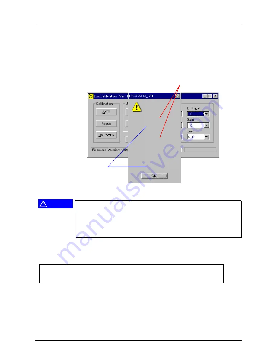
7.  Following screen appears to indicate that adjustment is completed.(Numbers in the figure are

just examples)


AWB Results
1:

Rg=364
Gg=128
Bg=195
AGC=1564288020
2:
Rg=370
Gg=128
Bg=186

AveRg=367
AveGg=128
AveBg=190
AGC=1564288020

Fixed value"128"

If either one of AGC
values indicates "241",
it is error.If so, adjust
again.


Figure 5-5. Screen After AWB and AGC Adjustment

CAUTION

„

„

If AGC=241 is indicated, it is error. In this case, it is necessary to
perform adjustment again. If 241 is indicated again after the re-
adjustment, it is necessary to replace CA1, CA2 boards, or CCD.

„

„

Values for Rg and Bg should be within from 200 to 400 respectively.
If their values are out of this range, same as above, it is necessary to
replace CA1, CA2 boards or CCD.

8.  Press OK on the screen.
9.  Adjustment result of AGC is changed from decimal number to hexadecimal number by using a

functional calculator.


In case of example in the figure above,

1 5 6 4 2 8 8 0 2 0(decimal number)


5 D 3 D 2 4 1 4


10.  The value which is changed to hexadecimal number becomes 4-byte(8 digits). From left, each

one byte(each 2 digits) is; AGC +2, AGC+1, AGC

±

0 and AGC

1. Therefore, in case of the

example in the figure above means;

AGC+2:

5D

AGC+1:

3D

AGC

±

0:

24

AGC

1:

14

Summary of Contents for PhotoPC700

Page 1: ...6 59 0 18 EPSON PhotoPC 700 RORU 6WLOO LJLWDO DPHUD EPSON PhotoPC700 4009250 ...

Page 2: ...e contents of this manual However should any errors be detected SEIKO EPSON would greatly appreciate being informed of them The above not withstanding SEIKO EPSON CORPORATION can assume no responsibility for any errors in this manual or the consequences thereof EPSON is a registered trademark of SEIKO EPSON CORPORATION General Notice Other product names used herein are for identification purpose o...

Page 3: ...NOT CONNECT THE UNIT TO A POWER SOURCE UNTIL INSTRUCTED TO DO SO WHEN THE POWER SUPPLY CABLE MUST BE CONNECTED USE EXTREME CAUTION IN WORKING ON POWER SUPPLY AND OTHER ELECTRONIC COMPONENTS WARNING 1 REPAIRS ON EPSON PRODUCT SHOULD BE PERFORMED ONLY BY AN EPSON CERTIFIED REPAIR TECHNICIAN 2 MAKE CERTAIN THAT THE SOURCE VOLTAGES IS THE SAME AS THE RATED VOLTAGE LISTED ON THE SERIAL NUMBER RATING PL...

Page 4: ... the theory of electrical and mechanical operations of the product CHAPTER 3 TROUBLESHOOTING Provides the step by step procedures for troubleshooting CHAPTER 4 DISASSEMBLY AND ASSEMBLY Describes the step by step procedures for disassembling and assembling the product CHAPTER 5 ADJUSTMENTS Provides Epson approved methods for adjustment CHAPTER 6 MAINTENANCE Provides preventive maintenance procedure...

Page 5: ...REVISION STATUS Rev Date Page s Contents A 1998 05 12 All First release ...

Page 6: ...Operation Specification 1 14 1 2 4 1 Basic Setting 1 14 OPERATING PRINCIPLES 2 1 OVERVIEW 2 1 TROUBLESHOOTING 3 1 OVERVIEW 3 1 DISASSEMBLY AND ASSEMBLY 4 1 OVERVIEW 4 1 4 1 1 Tools 4 2 ADJUSTMENT 5 1 OVERVIEW 5 1 5 1 1 Preparation for Adjustment 5 2 5 1 2 Initialization 5 3 5 1 3 Downloading Firmware 5 4 5 1 4 5100K AWB AGC Adjustment 5 5 5 1 5 Flange Back Adjustment 5 7 5 1 6 Color Matrix Adjustm...

Page 7: ...MAINTENANCE APPENDIX 7 1 1 Circuit Diagrams 7 1 7 1 2 Location Diagrams 7 2 ...

Page 8: ...PRODUCT DESCRIPTION 3 7 5 ...

Page 9: ...apacitor with large capacity is built on the SY1 board High serial interface is built in Data transmission speed is maximum 230Kbps However serial communication speed at PC side requires more than 19200bps White Balance Auto white balance Fixed white balance Exposure Control Program auto exposure Manual adjustment 4MB Flash Memory Standard is built Compact flash memory cards are available Picture ...

Page 10: ...ires flash light In this case focus the subject 1 5m forcibly and shoot it Shooting Range Macro mode 0 1m 0 5m Normal mode 0 5m infinity Shutter Mechanical shutter with electric iris control shutter Auto flash Forced flash 1 30 1 500 sec Auto Off 1 4 1 5000 sec Sensitivity Equivalent to ISO60 ISO110 at high sensitivity selected White Balance Full Auto TTL Color temperature 5100K at fixed mode Expo...

Page 11: ...nd by light red turns on and becomes impossible to shoot Although this is not malfunction some users misunderstand this phenomenon as malfunction The number of available images with various memories See Table below Table 1 3 The Number of Available Images with Optional Memories Setting Setting Display 4MB 10MB 15MB 20MB 24MB Standard 640x480 60 158 227 304 368 Fine 1280 x 960 19 50 72 97 116 Super...

Page 12: ...chrome 1280x960 Super fine Fine White balance Auto Fix Exposure adjustment Auto Manual 2 levels Sensitivity STD High Each setting mode range See Table below Table 1 4 Valid range at various setting modes Button off Main power operation off LCD Off Change to Playback Auto Power Off Off due to the end of battery life Macro Off Off Off Off Off Off Self timer Off Off Off Off Off Off Panorama Zoom Off ...

Page 13: ...n 30 minute However 3 hours are required to charge the capacitor full Menu Setting Other Panorama Zoom Continuous white balance setting Exposure setting Date Time setting Alert beep setting LCD brightness setting Energy saving setting image Information display mode Image play back mode normal or multi Magnification Erase all photos Copy photos Get Memory information Format memory cards Slide show ...

Page 14: ...ge PHYSICAL DIMENSION AND WEIGHT Dimension 142 5mm W x 69 8mm H x 48 8mm D Weight 280g without batteries and band ELECTRICITY DC input voltage AC Min DC 6 3V Max DC 8V OPERATION ENVIRONMENT TBD Temperature Operating 5 to 35 C Storage 20 to 60 C Humidity Operating 30 to 80 without condensation Storage 10 to 80 SAFTY STANDARD TBD Temperature VCCI Class B EXPANSION CONNECTOR Video signal output NTSC ...

Page 15: ...uto energy saving mode is invalid when using AC adapter After auto energy saving is operated the camera resumes continuity by half shutter operation ordinary focus lock VIEW MODE MENU Panorama Zoom Standard Panorama Zoom Shooting setting Continuous White balance Exposure Sensitivity Information Display On Off PLAYBACK MENU Setting Clock setting Year Month Date Time Beep sound On Off Color brightne...

Page 16: ...rinting Index printing Sicker printing Date printing Auto fine printing Support Printer EPSON Stylus Photo EPSON Stylus Photo700 EPSON Stylus Color 800 EPSON Stylus Color 600 and EPSON Stylus Photo EX All models mentioned above fixed at 720 dpi Recommended Paper A4 Photo Quality Glossy Film Photo Quality Glossy Paper Photo Quality Ink Jet paper Photo Quality Ink Jet Card A6 Photo Quality Paper Pri...

Page 17: ...andard 640x480 Fixed white balance Blinks Fine 1280 x960 Fixed white balance Blinks Super Fine 1280x960 Fixed white balance B W Fine 1280x960 Monochrome B W Super fine 1280x960 Monochrome Blinks alternatively Lights blinks alternatively at continuous shooting Monochrome mode B W Monochrome Macro mode Indicates at the macro mode Timer Indicates during the self timer is on Blinks when the self timer...

Page 18: ...ure adjustment value P2 P1 00 1 or 2 External memory error This error is indicated when installing or removing the external memory during image compression processing or LCD On at power on This error may destroy memory or image data Flash AUTO Auto flash mode Same as PhotoPC600 Forced flash mode Same as PhotoPC600 Forced flash off mode Same as PhotoPC600 Blinks Charging Charging to the capacitor f...

Page 19: ...W Fine No support No support No support Table 1 11 Indication in shooting LCD indication at View Mode LCD Indication Frame Color Mode Other LCD indication No indication Standard Green Macro Same as PhotoPC600 Indicates MACRO for a few seconds Blue Monochrome Same as PhotoPC600 Indicates MONOCHROME for a few seconds Orange Digital two times Zoom Same as PhotoPC600 Indicates ZOOM for a few sends Bla...

Page 20: ...ottom of the screen Shooting mode Monochrome This icon is indicated next to image quality incon Shooting mode Panorama This icon is indicated next to image quality icon Shooting mode Zoom This icon is indicated next to image quality icon Shooting mode Continuous This icon is indicated next to image quality icon Available shooting number is indicated at the center of screen bottom The number of pic...

Page 21: ...re 1 Not operate Not operate K J Not operate Erase images Only while processing image Erase currently indicated image Not operate Note1 It is necessary to set MANUAL in advance at the exposure adjustment setting in the View mode menu for this exposure adjustment function Note2 When K J function erase image is performed at View mode image can be erased only when the image is processing right after ...

Page 22: ...tead electrolytic capacitor can retain date and time setting temporarily up to 30 minutes However these data is erased 30 minutes after the battery energy runs out When this happens it is necessary to set date and time again PANORAMA SHOOTING REFER TO TABLE BELOW Table 1 14 Setting for Panorama Shooting Procedure Operation Switch Camera Mode Note 1 Set the LCD monitor mode switch to View Panorama ...

Page 23: ...Everytime SELECT switch is pressed it switches over Normal Multi 5 Press BACK switch selecting Multi photo Multi photo playback mode MAGNIFICATION INDICATION Table 1 18 Setting for Magnification Indication Procedu re order Operation switch Camera mode Note 1 Set LCD monitor mode SW to Playback Normal playback 2 Indicate the image to enlarge by using navigation switches In case of multi photo playb...

Page 24: ...ise it escapes from Erase photo mode 4 Erase only the selected image by pressing SELECT switch View mode Press BACK switch to cancel erasing photo CAUTION If you wish to erase a particular image or all images at once perform same procedure as that of PhotoPC600 Table 1 20 Operation to erase image s Procedure order Operation switch LCD monitor menu Note 1 Set the LCD monitor mode switch to Playback...

Page 25: ...r Operation Switch LCD monitor menu Note 1 Set the LCD monitor mode switch to View View mode 2 Press SELECT switch Panorama Zoom mode 3 Display Conditions mode by navigation switches Conditions mode 4 Press SELECT switch 5 Match the mark with an icon of exposure adjustment by using navigation switches Conditions mode selecting exposure 6 Everytime SELECT switch is pressed it changes over AUTO and ...

Page 26: ...ivity Make sure that High sensitivity is selected Conditions mode Sensitivity 7 Press BACK switch twice and go back to View mode Shooting available at View mode This setting is valid even the image on the LCD is turned off Table 1 24 Setting for Energy Saving Mode Procedure order Operation switch Camera mode Note 1 Set the LCD monitor mode switch to Playback Playback mode 2 Press SELECT switch Set...

Page 27: ...as those of PhotoPC600 Therefore refer to Chapter 2 on the Service Manual of PhotoPC600 for more details Although there is no changes about operating principles since each board is used exclusively for PhotoPC700 be careful not to order the parts of PhotoPC600 3 7 5 ...

Page 28: ...fication but actually approx 60 minutes by the super capacitor on the SY1 board Battery life is extended since the channel of power controller IC311 on the ST1 board is divided fine according to each elements 2 out of 4 flash memories on the CA2 board are completely determined as exclusive area for up loading data program Although AGC CDS are controlled by independent ICs respectively on the CA1 b...

Page 29: ...as those of PhotoPC600 refer to Chapter3 on the Service Manual of PhotoPC600 However since the adjustment items for PhotoPC700 are different from those of PhotoPC600 refer to Tabale3 1 and perform proper adjustments after repairing or replacing parts or boards 3 7 5 ...

Page 30: ... 3 1 Criterion of First Second Adjustment No Service Performed Required Adjustment Maintenance 1 Replacing CA1 board 1 Initialization 2 AWB AGC Adjustment 3 Color Matrix Adjustment Second maintenance Should be performed only by EPSON Co 2 Replacing or re assembling Lens Unit Optical filter or CCD 1 Initialization 2 AWB AGC Adjustment 3 Flange back Adjustment 4 Color Matrix Adjustment Second mainte...

Page 31: ...ocations of lead wires between boards are changed more or less be sure to solder those wires correctly as they were connected before Also since adjustment items for PhotoPC700 are different from those of PhotoPC600 make sure to perform corresponding adjustments by referring to Table4 1 and Chapter5 Only different points compared with PhotoPC600 are listed in this chapter 3 7 5 ...

Page 32: ...second maintenance is allowed to be done only by EPSON Co We do not guarantee the repair result by the others Refer to table below for distinction between first and second maintenance Table 4 1 Criterion of First Second Adjustment No Service Performed Required Adjustment Maintenance 1 Replacing CA1 board 1 Initialization 2 AWB AGC Adjustment 3 Flange back Adjustment 4 Color Matrix Adjustment Secon...

Page 33: ...Kelvin Color Viewer X 103058400 2 DscCal_12 Adjustment Program X Attached with this manual book 3 Simens star chart X Included in the end of this book 4 Precision Driver O 5 Soldering iron O B740200100 6 A pair of tweezers O B641000100 7 Oscilloscope O 8 Windows95 environment require 19200bps or higher for serial O 9 Color adjustment chart X 104268100 Note O means commercially available and X mean...

Page 34: ...CAUTION Adjustment items of PhotoPC700 are different from those of PhotoPC600 Here explains adjustment procedures only for PhotoPC700 So do not refer to Chapter5 Adjustment on the PhotoPC600 s Service Manual 3 7 5 ...

Page 35: ...5 1 Criterion of First 2nd Maintenance No Service Performed Required Adjustment Maintenance 1 Replacing CA1 board 1 Initialization 2 AWB AGC Adjustment 3 Flange back Adjustment 4 Color Matrix Adjustment Second maintenance Should be performed only by EPSON Co 2 Replacing or re assembling Lens Unit Optical filter or CCD 1 Initialization 2 AWB AGC Adjustment 3 Flange back Adjustment 4 Color Matrix Ad...

Page 36: ... Main electrolytic condenser C5412 Do not repair or replace other electric parts except for these 3 items Even if other electric parts are replaced the other adjustment procedure are not mentioned on the Service Manual 5 1 1 Preparation for Adjustment This section explains setting up of camera and PC before starting adjustment Follow the procedures below and complete the setting up before starting...

Page 37: ...gure 5 1 Button Location for Initialization 3 Press Initialize button 4 Since the screen to confirm the selection appears press Y Yes 5 Initialization starts After approximately 14 seconds of communication although the screen shows Complete communication between PC and camera still lasts another 5 seconds Therefore do not pull out the communication cables and also do not turn off the camera and ad...

Page 38: ... adjustment program 2 Following screen is indicated Button for Downloading Figure 5 2 Button Location for Downloading 3 Press Firmware button for downloading 4 Following screen appears ßæë ßæë Open Look in File Name N Files of Type T Open Cancel Figure 5 3 Selecting Firmware File 5 Input directory on the hard disk or FD which currently maintained Firmware is stored into Drive A and select Firmware...

Page 39: ...res how to input the values of auto white balance and auto gain controller This adjustment enables camera to automatically memorize color temperature which is input when the user emits light for flash Since these adjustment values to input in this section are stored with image data in the flash memory of the CA2 board it is necessary to perform this adjustment after performing initialization CAUTI...

Page 40: ...values indicates 241 it is error If so adjust again Figure 5 5 Screen After AWB and AGC Adjustment CAUTION If AGC 241 is indicated it is error In this case it is necessary to perform adjustment again If 241 is indicated again after the re adjustment it is necessary to replace CA1 CA2 boards or CCD Values for Rg and Bg should be within from 200 to 400 respectively If their values are out of this ra...

Page 41: ... 0 1 1 2 8 AGC 0 AGC 1 1 1 2 8 CAUTION If each calculated value is not within the range above adjust them again Also if re adjusted values are not within the rage again exchange CA1 CA2 boards or CCD 5 1 5 Flange Back Adjustment Here explains adjustment procedure to input a flange back value This adjustment adjusts focus to the subject Siemens star chart which is located a certain distance away fr...

Page 42: ...confirm the selection appears press Y Yes Be sure that adjustment value is within 34 to 60 Figure 5 7 Screen to confirm the Result After Adjustment 6 The camera shoots one time automatically and Flange back adjustment value appears on the screen 7 Be sure that adjustment value appeared on the screen 45 in the example above is within the range 34 to 60 Flange back Focus adjustment value 34 60 CAUTI...

Page 43: ...ent 3 Turn on color viewer and leave it for 10 minutes until brightness settles At this time set the volume of the color viewer to the maximum toward right direction 4 Locate the Color adjustment chart in front of the color viewer Locate the Color adjustment chart as if it covers the surface of the color viewer CAUTION Locate the color viewer where there is as less fluorescent light or light from ...

Page 44: ...ment values appears on the screen ÒÓ ÊÞñïæõ Ïâðòéñ ÒÓÊ Ñ º ÒÓÊ Ñ º ÒÓÊ Ñ ºª ÒÓÊ Ñ º µ Figure 5 10 Condition of the Program After Adjustment is done 11 Check each adjustment value by following instructions Each value range is listed below UVMAT0 Check if the value is within the range or not UVMAT1 If this adjustment value is below 128 check if that value is within the range or not If this adjustmen...

Page 45: ...MAINTENANCE Maintenance for PhotoPC700 is same as that of PhotoPC600 Refer to Chapter6 in the Service Manual of PhotoPC600 3 7 5 ...

Page 46: ... of connector pins of PhotoPC700 are not different from those of PhotoPC600 Therefore refer to Chapter7 of the PhotoPC600 Service Manual However since the circuit diagrams used for PhotoPC700 are only for PhotoPC700 refer to the diagrams in this chapter 3 7 5 ...

Page 47: ...PhotoPC700 Chapter7 Appendix Rev A 7 1 7 1 1 Circuit Diagrams Following pages show circuit diagrams mounted in the PhotoPC700 1 SY1 board 2 CA2 board 3 CA1 board and 4 ST1 board ...

Page 48: ...PhotoPC700 Chapter7 Appendix Rev A 7 2 7 1 2 Location Diagram Following pages show the locations of electric parts mounted on the each board CA2 CA1 SY1 TB1 and ST1 boards ...

Page 49: ...4 3 5 7 6 2 1 8 9 10 19 20 21 22 23 25 24 18 16 17 14 11 12 13 101 101 101 101 100 100 100 100 100 100 100 100 102 102 102 102 29 ...

Page 50: ...11 13 14 12 16 17 18 9 8 10 7 6 5 1 4 2 3 19 20 21 22 15 101 101 101 105 105 105 105 105 100 103 104 100 100 100 100 100 105 23 24 ...

Page 51: ...203 200 150 151 PACKING MATERIALS FOR CP 600 PHOTO PC 700 01 02 03 04 ...

Reviews: