PhotoPC 2100Z
Revision E
Adjustment
Adjustment
71
5.3.7 USB ID Writing
In this adjustment, the USB ID is written in flash memory on the Main Circuit Board.
When the Main Circuit Board has been replaced with a new one, the camera can not
use the USB ID which is stored on the old circuit board. Therefore, make this
adjustment to register a new USB ID on the new circuit board.
Adjustment Procedure
1.
Connect the camera to PC by the serial cable to the camera via RS-232C interface. (See
"LCD (Brightness) Adjustment" on page 65)z
2.
Turn on power to the PC and run the adjustment program (CRT21sp.exe).
3.
Insert into the camera the CF card in which the USB ID writing program has been
installed.
4.
Hold down the F Button and Shutter Button together and press the Playback Button.
Then power to the camera will turn on and the viewfinder LED will blink.
5.
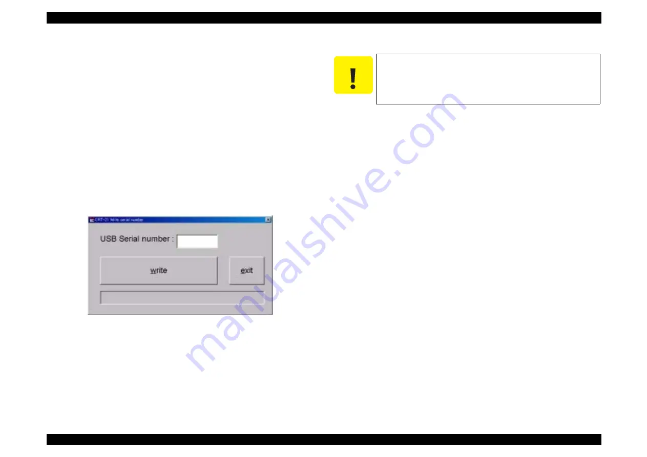
The window as shown below will appear. Then enter the 6-digit serial number.
6.
Upon completion of input, press the “W” key on the keyboard of the PC (“write”
button), and the PC and the monitor of the camera will display “OK”.
7.
Pressing the Shutter Button fully will turn off power to the camera to complete the
adjustment.
8.
Remove the CF card from the camera.
9.
Disconnect the AC adapter and the communication cable from the camera.
10. Pressing the “e” key (“exit” button) will complete the adjustment program.
C A U T I O N
If the display shows “A camera number can't be inputted” during
USB ID writing, it signifies that the USB ID is not written
successfully. In such a case, follow the USB ID writing procedure
again.
Summary of Contents for PhotoPC 2100Z
Page 1: ...EPSONPhotoPC2100Z Digital Still Camera SERVICE MANUAL SEDC01002 ...
Page 9: ...C H A P T E R 1 PRODUCTDESCRIPTION ...
Page 42: ...C H A P T E R 2 OPERATINGPRINCIPLES ...
Page 44: ...PhotoPC 2100Z Revision A Operating Principles Overview 38 ...
Page 47: ...PhotoPC 2100Z Revision A Operating Principles Overview 41 PS_block7019e pdf ...
Page 49: ...C H A P T E R 3 TROUBLESHOOTING ...
Page 52: ...C H A P T E R 4 DISASSEMBLYANDASSEMBLY ...
Page 65: ...C H A P T E R 5 ADJUSTMENT ...
Page 78: ...C H A P T E R 6 MAINTENANCE ...
Page 80: ...C H A P T E R 7 APPENDIX ...
Page 82: ......
Page 87: ......
Page 88: ......
Page 90: ......
Page 91: ......
Page 92: ......
Page 93: ......
Page 94: ......
Page 95: ......
Page 96: ......
Page 97: ......
Page 98: ......
Page 99: ......
Page 100: ......
Page 108: ......


