background image

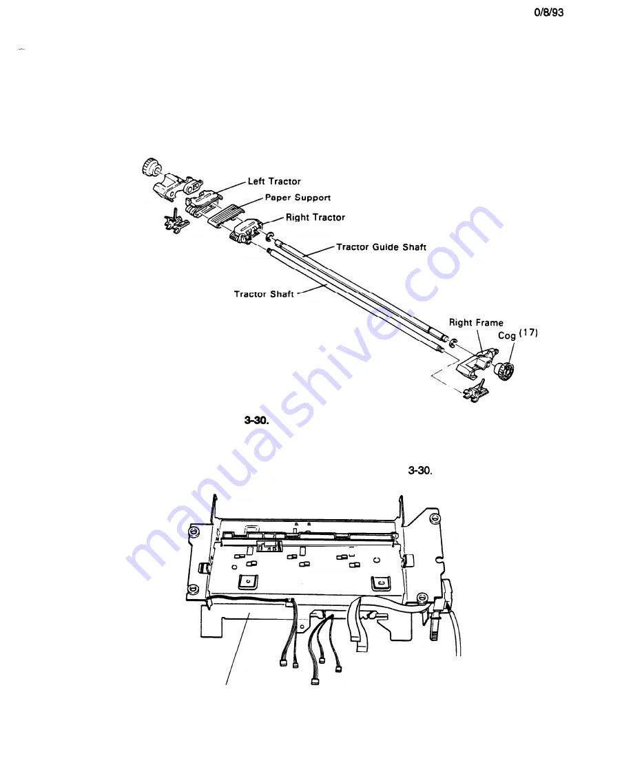
3.2.5.15 Disassembling the Tractor Unit

1.

Remove the tractor unit from the printer.

2.

Remove the cog (17 mm) from the tractor shaft.

3.

Remove the right tractor frame from the tractor shaft and the 

tractor 

guide shaft;

4.

Remove E-ring 6 from the tractor shaft.

5.

Remove the right tractor, the paper support unit, and the left tractor from the tractor shaft and tractor

guide shaft.

Figure 

 Disassembling the Tractor Unit

3.2.5.16 Arranging the Cables

When you assemble the printer, arrange the cables as shown in Figure 

n

Printer Mechanism (Bottom)

Figure 3-30. Arranging the Cables

3-23

Summary of Contents for LQ-1170

Page 1: ...LQ 1170 24 PIN DOT MATRIX PRINTERS TM LQ8 1170 ...

Page 2: ...L Q 8 7 0 1 1 7 0 SERVICE MANUAL EPSON T Printed on recycled paper ...

Page 3: ...ject to change without notice All efforts have been made to ensure the accuracy of the contents of this manual However should any errors be detected SEIKO EPSON would greatly appreciate being informed of them The above notwithstanding SEIKO EPSON can assume no responsibility for any errors in this manual or the consequences thereof Copyright 1991 by SEIKO EPSON CORPORATION Nagano Japan ...

Page 4: ...L DO NOT CONNECT THE UNIT TO A POWER SOURCE UNTIL INSTRUCTED TO DO SO WHEN THE POWER SUPPLY CABLE MUST BE CONNECTED USE EXTREME CAUTION IN WORKING ON POWER SUPPLY AND OTHER ELECTRONIC COMPONENTS WARNING 1 REPAIRS ON EPSON PRODUCT SHOULD BE PERFORMED ONLY BY AN EPSON CERTIFIED REPAIR TECHNICIAN 2 MAKE CERTAIN THAT THE SOURCE VOLTAGE IS THE SAME AS THE RATED VOLTAGE LISTED ON THE SERIAL NUMBER RATIN...

Page 5: ... 1 Provides a general product overview lists specifications and illustrates the main components of the printer Chapter 2 Describes the theory of printer operation Chapter 3 Includes a step by step guide for product disassembly and assembly Chapter 4 Includes a step by step guide for adjustment Chapter 5 Provides Epson approved techniques for troubleshooting Chapter 6 Describes preventive maintenan...

Page 6: ...Revision Level Revision Date I 1st printing I 7 23 91 I I ViSC d I 10 g 91 I 1 2ndprhting I 3 17 92 I ...

Page 7: ...REV A TABLE OF CONTENTS CHAPTER 1 CHAPTER 2 CHAPTER 3 CHAPTER 4 CHAPTER 5 CHAPTER 6 APPENDIX GENERAL DESCRIPTION OPERATION PRINCIPLES DISASSEMBLY AND ASSEMBLY ADJUSTMENTS TROUBLESHOOTING MAINTENANCE vi ...

Page 8: ... Form Override Function 1 21 1 6 4 Error Conditions 1 21 1 6 5 Buzzer Operation 1 21 1 6 6 Printer Initialization 1 22 1 6 7 Default Values 1 22 1 6 8 Paper Loading and Ejection 1 23 1 6 9 Tear off Function 1 23 1 6 10 Paper Thickness Lever Operation 1 24 1 6 11 Printer Protection for Heavy Duty Printing 1 25 1 7 MAIN COMPONENTS 1 26 1 7 1 C060 MAIN C061 MAIN and C060 MAIN B Board Main Control Cir...

Page 9: ... Mechanism 1 29 Figure 1 17 Housing 1 30 LIST OF TABLES Table 1 1 Optional Interface Cards Table 1 2 Optional Units 1 1 1 2 Table 1 3 Specifications for Single Sheet Paper 1 4 Table 1 4 Specifications for Single Sheet Multi Part Forms Carbonless Duplicating Paper 1 5 Table 1 5 Specifications for Continuous Paper 1 5 Table 1 6 Specifications for Envelopes 1 5 Table 1 7 Specifications for Labels 1 5...

Page 10: ...ing the front bottom or rear paper entrance Auto backout and auto loading when using the front or rear paper entrance Ability to use continuous paper without removing the cut sheet feeder Ability to use the standard tractor in three positions two push tractor positions and one pull tractor position Single sheet paper Two ways to insert single sheet paper using the front or top paper entrance Auto ...

Page 11: ...del No Description C80637 Single bin cut sheet feeder C80638 High capacity cut sheet feeder I C80020 1 Tractor 7753 Fabric ribbon cartridge 7768 Film ribbon cartridge Table 1 2 1 Optional Units for LQ 1170 1 Model No Description C80639 Single bin cut sheet feeder C80640 High capacity cut sheet feeder I C8002 1 l Tractor I r I 7754 Fabric ribbon cartridge I 7770 Film ribbon cartridge When the last ...

Page 12: ... feeding front and bottom paper entrances Push pull tractor feeding front and rear paper entrances 1 6 inch 1 8 inch or programmable in units of 1 360 inch Friction feeding front or top paper entrance Tractor feeding front bottom or rear paper entrance Friction feeding without cut sheet feeder 59 0 msec for a 1 6 inch line feed 3 6 inches per second ips during continuous feeding Friction feeding w...

Page 13: ...o the front rear or bottom paper entrance 0 Release the friction feed mechanism l Remove the paper tension unit and attach the pull tractor 0 Make sure there is no slack in the paper between the platen and the pull tractor 0 Carefully align the pull tractor and push tractor sprockets l Paper for multiple copies must be spot pasted beyond the perforation between the sprocket holes 0 Use only carbon...

Page 14: ...ickness within the printing area must be less than 0 25 mm 0 0098 in Weight 12 to 24 lb 45 to 9 1 g m2 Quality Bond paper standard paper air mail Copies Not available NOTES 0 Printing on envelopes is available only at normal temperatures 0 Load envelopes only into the top paper entrance 0 Keep the longer side of the envelope horizontal when you insert it 0 Place the left edge of a no 6 envelope at...

Page 15: ... accuracy cannot be assured within 26 mm 1 02 in from the bottom edge of the paper For front insertion paper feeding accuracy cannot be assured within 47 0 mm 1 85 in from the bottom edge of the paper Figure 1 3 Printable Area for Single Sheet Paper Prmlable area I 4 9mmtO 35 or more 9mm10 35 or more I Prmtable area 0 0 0 0 0 0 0 0 0 0 l 0 XYZ 0 0 0 o_ 0 0 7Gq 0 0 0 0 0 0 l 1 13 mm 0 51 in or more...

Page 16: ...lures MCBF 5 million lines excluding printhead Mean time between failures MTBF 4000 power on hours POH at 25 duty 80 column Printhead life Safety approvals Mean time between failures MCBF 6000 power on hours POH at 25 duty 136 column 200 million strokes black ribbon 100 million strokes film ribbon Safety standards UL1950 with D3 U S version CSA22 2 220 EN 60950 TUV European version Radio frequency...

Page 17: ...n draft mode at 10 cpi 10 Megohms minimum at 500 VDC between AC line and chassis 1250 VAC rms for one minute or 1500 VAC rms for one second between AC line and chassis 5 to 35 degrees C 41 to 95 degrees F operating 30 to 65 degrees C 22 to 149 degrees F in shipping container 10 to 80 RH operating 5 to 85 RH storage 1 G within 1 ms operating 2 G within 1 ms storage 0 25 G 55 Hz maximum operating 0 ...

Page 18: ...SON Roman 10 12 15 proportional EPSON Sans Serii 10 12 15 proportional EPSON Courier 10 12 15 EPSON Prestige 10 12 EPSON Script 10 12 EPSON Script C proportional OCR B 10 EPSON Orator 10 EPSON Orator S 10 EPSON Draft 10 12 15 EPSON Roman 8 to 32 pt EPSON Sans Serif 8 to 32 pt Printing modes It is possible to select and mix the following printing modes except 15 cpi condensed which is not available...

Page 19: ...l dot space of characters is not set No bit image is sent to the printer Super subscript is not selected The printer switches back to normal mode to print emphasized condensed or download characters and bit images Printing speed See Tables l 8 and l 9 Printing columns See Table 1 8 Character matrix See Table l 10 Character size See Table l 10 Table 1 8 Printing Text Mode 80 13 Column cpi character...

Page 20: ...REV A Table 1 9 Printing Bit Image Mode 80 136 Column dpi dots per inch ips inches per second 1 11 ...

Page 21: ...360 NOTES l HDD is the horizontal dot density in dots per inch l Face matrix and character size indicate the size of the maximum character This value depends on the paper the ribbon and other variables 0 Unit ESC sp which also can be sent as unit followed by the character string CHRS h20 indicates the minimum length to be added to the right of the character specified with the ESC sp control code l...

Page 22: ...13 14 15 16 17 18 19 20 21 22 23 24 Subscript character R I G H T S P A C E 1 2 3 4 5 6 7 8 9 10 11 12 13 14 15 16 17 18 19 20 21 22 23 24 Ascender area Descender area R I G Ii T S P A C E 29 dots Typical LQ excluding 15 pitch 15 dots for 15 pitch and condensed LO 4 Character width CW 3 6 dots 10 CPI 360 DPI 3 0 dots 12 CPI 360 DPI 2 4 dots 15 CPI 360 DPI 2 1 dots condensed 10 CPI 3 6 0 DPI 18 dot...

Page 23: ...No Signal Name Return Pin No Dir Function 1 STROBE 19 IN STROBE pulse to read the input data Pulse width must be more than 0 5 ps Input data is latched at the falling edge of this signal 2 DATA 1 20 IN Parallel input data to the printer 3 DATA 2 21 IN HIGH level means data 1 4 DATA 3 22 IN LOW level means data 0 5 DATA 4 23 IN 6 DATA 5 24 IN 7 DATA 6 25 IN 8 DATA 7 26 IN 9 DATA 8 27 IN IO ACKNLG 2...

Page 24: ...has occurred in the printer Ground for twisted pair grounding Not used Always HIGH Pulled up to 5 V through 3 3K ohm resistor If LOW when the printer is initialized DCl DC3 control is disabled NOTES Dir indicates the direction of the signal flow as viewed from the printer Return Pin No denotes a twisted pair return line The cable used must be shielded to prevent noise All interface conditions are ...

Page 25: ...form feed whether the printer is in the PAUSE or the RUNNING condition Press this button and the ALT button at the same time to use the micro reverse feed function 4 LOAD EJECT button Press this button to load or eject paper See Section 1 6 8 Paper Loading and Ejection Press this button and the ALT button at the same time to use the micro forward feed function 5 TEAR OFF BIN l BIN 2 button When th...

Page 26: ...as received data from the host machine 5 PAPER OUT red Lit when the paper out detector detects that there is no paper See Section 1 6 3 Paper out Detection and Form Override Function 6 MULTI PART green Lit when the paper thickness lever is positioned at the fourth step or higher 7 BIN 1 green Lit when bin 1 is selected 8 BIN 2 green Lit when bin 2 is selected 8 FONT green Draft Courier Roman Sans ...

Page 27: ...l Table 1 12 DIP Switch Set 1 SW1 Description I O N I OFF Factory Setting 1 1 ON 2 International and PC character set selection See Table l l 4 ON 3 ON 4 Character table selection Graphic Italic OFF 5 Graphics direction Unidir Bidir OFF 6 High speed draft mode Invalid Valid OFF 7 1 Input buffer Invalid Valid I OFF 8 One inch skip continuous paper I ON I OFF I OFF Table 1 13 DIP Switch Set 2 SW2 No...

Page 28: ...you turn on DIP switch l 4 and use ESC 0 to select the italic character table the country setting becomes U S When you turn off DIP switch l 4 and use ESC t 1 to select the graphics character table the PC setting becomes 437 Table l l 5 Page Length 2 1 2 2 Page Length OFF OFF 11 inches ON OFF 12 inches OFF ON 8 5 inches ON ON 70 6 inches 1 52 Jumpers If jumper 3 is connected to GND the SLCT IN sig...

Page 29: ...t i Invalid on Receive buffer SWl 7 V a l i d o f f Invr ljd 0 1 1 1 i n c h s k i p SWI 8 Invalid o f f i 1 I1 h swz 1 2 2 o f f o f f Figure 1 8 Self Test 1 6 2 Hexadecimal Dump Function To enter hexadecimal dump mode turn on the printer while pressing both the LOAD EJECT and the LINE FEED FORM FEED buttons In hexadecimal dump mode the printer prints the hexadecimal representation of the input d...

Page 30: ... Error Conditions If any of the following error conditions are detected the printer automatically enters the PAUSE condition 0 The home position is not detected at printer mechanism initialization 0 The home position is detected during printing 0 The PAUSE button is pressed and the printer enters the PAUSE condition 0 A paper out is detected after the printer performs a paper loading operation If ...

Page 31: ...e effect 3 Control panel initialization Pressing the PAUSE and ALT buttons at the same time initializes the printer but does not perform functions a and c above The last SelecType settings still take effect 1 6 7 Default Values When the printer is initialized the following default values take effect Page position Left and right margins Line spacing Vertical tabs Horizontal tabs Family number of ty...

Page 32: ...es press the LOAD EJECT button several times Each time you press the LOAD EJECT button the printer reverse feeds one page When the paper is at the current setting for the top of form position the top of form adjustment function is valid for the setting a new top of form position At this time pressing the LOAD EJECT button moves the paper forward and pressing the LINE FEED FORM FEED and ALT buttons...

Page 33: ... the paper automatically returns to its original position and printing starts If you press the TEAR OFF button again while the printer is advancing the paper to the tear off position the paper returns to its original position whether the printer is in the PAUSE or the RUNNING condition 1 6 10 Paper Thickness Lever Operation You must set the paper thickness lever the adjust lever to the proper posi...

Page 34: ...s the printhead temperature decreases print speed increases to the normal speed If the printhead temperature continues to increase at the lower speed the printer stops printing The printer stops or resumes printing as the printhead temperature increases or decreases If the voltage supplied to the head drive circuit drops below its minimum limit as a result of heavy duty printing printing is interr...

Page 35: ... board is unnecessary CO60 MAIN B New boards for the LQ 870 and LQ 1170 There is a different CO60 MAIN B board for the LQ 870 than is used for the LQ 1170 These boards combine main board and driver board CO60 DRV board is unnecessary and can replace any previous board for a printer of the same carriage width CO60 MAIN board original CO61 MAIN board main control board LQ 1170 l CO60 MAIN B board ma...

Page 36: ...he LQ 870 or the LQ 1170 All these boards contain a TMP90CO4 8 bit CPU an EO5A49BB gate array a PROM 512K a PSRAM 256K a mask ROM 1 M and an EEPROM In addition the CO61 and CO60 MAIN B also include the components and circuits built into the CO60 DRV board The CO60 MAIN B board for the LQ 1170 contains an SRAM in location 5A which is not mounted in the CO60 MAIN B board for the LQ 870 EEP Gere Arra...

Page 37: ...icator LEDs and DIP switches Figure 1 13 CO60 PNL Board 1 7 3 C060 PSB Board Power Supply Circuit Board The power supply unit consists of a switching regulator circuit that converts the AC line voltage to the DC vottages for example 35 V and 5 V used by the printer The CO60 PSB board uses a 120 V input type Figure l 14 CO60 PSB Board 1 28 ...

Page 38: ... and the CO60 MAIN B boards Figure l 15 CO60 DRV Board 1 7 5 M 5D10 5D60 Printer Mechanism The M 5D10 5D60 printer mechanism was developed specifically for use with LQ 870 1170 Its components include the carriage motor carriage mechanism paper feed motor paper feed mechanism ribbon feed mechanism printhead and sensors The printer mechanism provides four ways to insert paper Figure 1 16 M 5D10 5D60...

Page 39: ...housing consists of the upper lower and front cases The front case houses the control panel board The lower case contains the printer mechanism main control circuit board and power supply circuit board IY LQ 870 Figure l 17 Housing 1 30 ...

Page 40: ... Circuit 2 20 2 3 6 Printhead Drive Circuit 2 21 2 3 7 Parallel Interface Circuit 2 22 2 3 8 EEPROM Control Circuit 2 22 Figure 2 1 Figure 2 2 Figure 2 3 Figure 2 4 Figure 2 5 Figure 2 6 Figure 2 7 Figure 2 8 Figure 2 9 Figure 2 10 Figure 2 11 Figure 2 11 1 Push Pull Tractor Feeding Using the Rear Entrance 2 7 Figure 2 12 Pull Tractor Feeding Using the Bottom Entrance 2 8 2 i How the Printhead Wor...

Page 41: ...nce 2 10 Ribbon Advance Mechanism 2 11 Power Supply Circuit Block Diagram 2 13 Control Circuit Block Diagram 2 14 Data Flow 2 15 Reset Circuit Block Diagram 2 17 RESET Signal Timing 2 18 Sensor Circuit Block Diagram 2 18 Carriage Motor Drive Circuit 2 19 Paper Advance Motor Drive Circuit 2 20 Printhead Drive Circuit 2 20 Head Drive Signal Output Timing 2 21 Parallel Interface Circuit 2 22 EEPROM C...

Page 42: ... induced force causes the plate to approach the coil rod and the associated dot wire is rapidly ejected to impact on the platen 3 The dot wire presses the ink ribbon up against the paper as it hits the platen and in this way prints a dot on the paper 4 As soon as the current through the coil is switched off the force induced in the coil rod stops The plate then returns to its original position its...

Page 43: ...arriage Movement The paper thickness adjustment lever allows the printer to use paper of different weights or thicknesses The user can change the platen gap on the carriage guide shaft by moving this lever Changing the position of the lever turns the carriage guide shaft and moves the carriage either toward or away from the platen Moving the paper thickness adjustment lever to the fourth position ...

Page 44: ...OK No Push Tractor OK OK No Pull Tractor OK OK OK Push pull Tractor OK OK No TOP OK No No No 2 1 3 1 Paper Feeding Mechanisms This section describes how the friction and tractor feed mechanisms advance paper in the printer Friction Feed Method The paper is held between the platen and the paper advance roller and between the paper eject roller and the paper eject unit cover The paper feed pinion ge...

Page 45: ...the direction of the black arrow results in pushing the paper through the mechanism During tractor feeding the release lever is set to the tractor position to disengage the friction drive This releases the pressure between the paper advance roller and the platen Figure 2 5 illustrates push tractor operation Paper Continuous w _ _ Paper Tension Roller I ransmlsslon tiear ractor Reduction Gear Paper...

Page 46: ...ottom paper entrance Paper Continuous Platen v Tractor Gear Paper Tension Roller ransmission Gear Paper Feed Reduction Gear Figure 2 6 Pull Tractor Operation Push Pull Tractor Method The push pull tractor method is a combination of the push tractor and pull tractor methods In push pull tractor feeding the printer uses two tractors one in front of and one behind the paper entrance to advance the pa...

Page 47: ...er Insertion Entrances This section describes how the printer feeds paper when you use each of the paper insertion entrances Top paper insertion entrance When you insert paper into the top entrance the printer uses friction feeding to advance the paper The printer has two paper out detectors the front paper out detector which is in front of the printer mechanism and the rear paper out detector whi...

Page 48: ...push pull tractor method to advance the paper The rear paper out detector senses when the paper runs out Paper Continuous Paper Tension Roller Push Tractor aper End Sensor Rear Paper Feed Roller Figure 2 10 Push Tractor Feeding Using the Rear Entrance Pull Tractor Paper Feed Roller Figure 2 11 Pull Tractor Feeding Using the Rear Entrance 2 7 ...

Page 49: ...Rear Entrance Bottom paper insertion entrance When you insert paper into the bottom entrance the pull tractor advances the paper The front paper out detector senses when the paper runs out Pa per Continuous Paper Feed Roller 1 Paper End Sensor Front From Bottom Insertion Figure 2 12 Pull Tractor Feeding Using the Bottom Entrance 2 8 ...

Page 50: ... the push and pull tractors to advance the paper The front paper out detector senses when the paper runs out Paper End Sensor PF Paper Tension Roller From Front Insertion Figure 2 13 Friction Feeding Using the Front Entrance Paper Continuous Printhead Paper End Sensor Front From Front Insertion Figure 2 14 Pull Tractor Feeding Using the Front Entrance 2 9 ...

Page 51: ... Paper End Sensor I Push Tractor ape r i Roller PF Drive Roller Figure 2 14 l Push Tractor Feeding Using the Front Entrance Paper Continuous From Front lnserti Paper End Sensor Figure 2 14 2 Push Pull Tractor Feeding Using the Front Entrance 2 10 ...

Page 52: ...mission gear t Planet gear 1 4 Planet gear 2 0 Ribbon driving gear The ink ribbon within the cartridge case is an endless ribbon The pressure of the ribbon grip roller holds the ribbon against the ribbon advance roller The ribbon advance roller is linked to the ribbon drive gear and winds the ink ribbon The ribbon brake spring is attached to the exit slot of the cartridge case It prevents slack in...

Page 53: ...Ds Paper advance motor hold 2 2 2 Supply Circuit Operation Figure 2 l 6 shows the power supply circuitry in block diagram form AC power feeds into the printer from the external power source A filter circuit removes the noise The AC voltage then undergoes full wave rectification and is smoothed to produce the direct current supply voltage This voltage is fed through a switching circuit and secondar...

Page 54: ...r from damage that might occur if the secondary circuitry of the 35 VDC line short circuits If a voltage drop is detected it stops switching circuit operation which stops the output of the 35 VDC line Power Supply Board r P r i m a r y i Secondary p F p t5VDC I I _ Full wave q Rectificatio Circuit t _ t AC Input III1I 5 line I Voltage Overload I Protection I I C i r c u i t I I I I I I 35 hne I Vo...

Page 55: ... gate array contains various memory management functions that assign memory and I O areas The PU4135 rationalizes and simplifies the circuitry and contains all the driver circuits for driving the printer mechanism on five chips Figure 2 17 shows the control circuits in block diagram form CO60 PNL Control Panel CO60 MAIN CO61 MAIN CO60 MAIN B Parallel EEPROM I F SC Optional FP Bl _ __ _ G A EOSWBB ...

Page 56: ...ne of data sequentially The CPU transfers the print data to the printhead drive circuit and sends the printhead drive pulse to the printhead drive circuit The length of the pulse corresponds to the printhead drive voltage Then the printhead drive circuit outputs the printhead drive signal P r i n t Host Data I Computer 7 35V Line t CPU t v i Data line Data Latch and Data Output I STK 6022B I P r i...

Page 57: ...ol Unit Panel Control Unit EEPROM Control Unit General Output Unit HPW Differential Unit HPW Pulse Limit Unit Bit manipulation unit Head Control Unit Internal Clock Generate Unit Internal I O and MMIO Decode Unit PU4135 IC8 IC13 PROM 3A RAM 4A 5A MROM 1A Mask ROM 2A EEPROM 5c V r e f C i r c u i t 1C TL43 1 Output Data Multiplex and input Data Latch Unit This is a drive circuit for the printhead I...

Page 58: ...lse Then the electrical charge through the resistor R49 in the condenser C28C29 is discharged After this E05A49 receives the THLD signal and outputs the RESET signal After a certain time has elapsed the charge in the condenser builds up again The THLD signal is canceled and then the RESET signal is canceled When the CPU performs a reset CPU self reset The CPU outputs the RESET signal if there is a...

Page 59: ...e the TEMP2 signal and other signals such as the CRHOME signal are sent directly to the CPU The 35 V line signal passes through the reset circuit before it reaches the CPU Terminals P50 to P55 in the CPU are used for the A D converter The Vref circuit generates the A D converter reference voltage Vref CPU 1C P31 L E V E R 3 1 RESET NMI PST 529C 36 35V Line 17 P50 T 2 8 4 7 4 1 v V r e f Vref Circu...

Page 60: ...nals are sent to HOLD to M on the SLA7024M The SLA7024M sets the coil current to correspond to the carriage motor speed The printer uses ports P60 to P63 in the CPU exclusively as control ports for the stepping motor CPU 2C P60 P 6 1 P 6 2 P63 Data Bus PO Pl P2 E05A49 48 SLA7024M IC15 GRAIN CRA CRBIN CRB CR A CR A CR B CR B HOLD L M GP f C o i l C u r r e n t CR Motor Coil Current GND Figure 2 22 ...

Page 61: ...U 150 1 according to the phase data the CPU sends When the paper advance motor is running the voltage supplying the coil of the paper advance motor is i 35 V When the paper advance motor is not running and is in hold status the supply voltage to the coil is 5 V Switching between these two supply voltages occurs at the PFCOM terminal of the PU 150 1 when PFENB is turned on or off CPU 1C P70 P72 P71...

Page 62: ...oltage levels through the length of the pulses These signals are output to the head for each of the sections of print data that were created by dividing the data three times before sending it By sampling the 35 V line voltage and determining the length of the head drive signal it is possible to keep the energy supplied to the head constant If the voltage of the 35 V line is HIGH the CPU shortens t...

Page 63: ...signal so that the printer is ready to receive more data from the host computer Parallel I F DO 7 D I N O 7 D A T A O 7 STB ii STROBE _ r _ _ _ _ _ _ _ _ _ _ _ I I I I B U S Y e BUSY D O 7 P82 E05A49 48 CPU 2C Figure 2 26 Parallel Interface Circuit 2 3 8 EEPROM Control Circuit Figure 2 27 shows the EEPROM control circuit in block diagram form The EEPROM contains information such as the top of form...

Page 64: ...e FFC 3 14 3 2 5 4 Removing the Carnage 3 15 3 2 5 5 Removing the Platen 3 16 3 2 5 6 Removing and Disassembling the Right Frame 3 17 3 2 5 7 Removing and Disassembling the Left Frame 3 17 3 2 5 8 Removing and Disassembling the Paper Guide Support Assembly 3 18 3 2 5 9 Removing and Disassembling the Carnage Guide Assembly 3 18 3 2 5 10 Removing the Home Position Sensor 3 20 3 2 5 11 Removing the R...

Page 65: ...embling the Carriage Guide Assembly Figure 3 23 Insertion Direction for Plain Washer Figure 3 24 Inserting the Release Shaft Figure 3 25 Removing the Home Position Sensor Figure 3 26 Removing the Rear Paper Out Detector Figure 3 27 Removing the Front Paper Out Detector Figure 3 28 Removing the Platen Gap Sensor Figure 3 29 Removing the Release Sensor Figure 3 30 Disassembling the Tractor Unit Figu...

Page 66: ...peration use only the recommended tools for maintenance work Adjust the printer only as described in this manual 3 1 2 Tools Tables 3 l and 3 2 list the tools you need when disassembling assembling or adjusting the printer Use only tools that meet these specifications Table 3 1 Recommended Tools Tool Part No Round nose pliers B740400100 Nippers B740500100 Tweezers B741000100 Soldering iron B740200...

Page 67: ...e motor running at the 0 Checked 0 Not necessary correct temperature and not overheating Paper path Is the paper in the printer feeding 0 Checked 0 Not necessary smoothly Is the tractor feeding the paper correctly 0 Checked 0 Not necessary Is the paper path clear of all obstructions 0 Checked 0 Not necessary Is the platen free of damage 0 Checked 0 Not necessary Ribbon Is the ribbon mask free of d...

Page 68: ...nt S tight screw CBB C Cross recessed Bind head Cone point B tight screw CB Cross recessed Bind head screw CBS O Cross recessed Bind head S tight screw with Outside toothed lock washer Table 3 5 Types of Screws and Abbreviations Head Body Washer assembled TOP Side Cross recessed head 1 fjind 1 tjormal 1 _Plain washer 0 II OENl c I 2 S tight Slotted head with Notch cl 2 _Outside toothed lock washer...

Page 69: ...s CAUTION Before disassembling any part of the printer read the warnings in Section 3 1 Before disassembling any part of the printer remove the paper and the ribbon cartridge Disassembly consists of the following procedures Removing the printhead Removing the case Removing the electrical circuits Removing the printer mechanism Disassembling the printer mechanism Diagrams in the appendix show how t...

Page 70: ...the paper eject cover Figure 3 2 Removing the Printer and Paper Eject Cover 3 Remove the 2 screws that secure the printhead to the carriage Lift out the printhead 4 Disconnect the upper and lower FCCs from the printhead Printhead Head Cable Figure 3 3 Removing the Printhead ...

Page 71: ... then remove the front case CB M3X8 Figure 3 4 Removing the Front Case 3 2 2 2 Removing the Upper Case Remove the printer cover the paper tension unit the tractor and the paper advance knob Remove the 2 CBS C M3X12 screws that attach the optional interface card cover or remove the 2 thumb screws that attach the optional interface then remove the cover or interface card CBS C M3 X 12 Figure 3 5 Rem...

Page 72: ...ined at the factory either for the LQ 870 or the LQ 1170 Section 3 2 3 4 describes removal of the CO60 PSB board and Section 3 2 3 5 describes removal of the CO60 PNL board 3 2 3 1 Removing the Driver Board CO60 DRV Board This board is used with the CO60 MAIN board only It is unnecessary with the CO61 or CO60 MAIN B board 1 Remove the upper case as described in Section 3 2 2 2 2 Disconnect the cab...

Page 73: ...N4 and CN6 from the main board 5 Remove the 3 CBB C M3 X 12 screws and 2 CB Ml X 8 screws that hold the main board to the lower case then remove the main board CBB C M3 x 12 Screws C B CB M3 8 Scre CO60 MAIN Board Figure 3 7 Removing the CO60 MAIN Board Assembly and Adjustment Note After replacing the main board you must adjust the bidirectional print position to ensure that bidirectional printing...

Page 74: ...N4 through CN16 on the main board 5 Remove the 2 CBS B M3 x 8 screws securing the interface ground plate 6 Remove the 3 CBB M3 x 12 screws attaching the main board to the lower case Then remove the main board CBB M3 X 12 CBS M3 61 CBS Mu3 x 8 SHlELD PLATE Figure 3 8 Removing the CO61 MAIN or CO60 MAIN B Board Assembly and Adjustment Note After replacing the main board you must adjust the bidirecti...

Page 75: ... 3 9 Special Extractor Tool 1 Remove the upper case as described in Section 3 2 2 2 2 Remove the mechanism unit as described in Section 3 2 4 3 Disconnect the cable from CNl and CN2 on the PSB 4 Remove the 2 CBS C M3 X 12 one way screws and the 2 CBS O M3 X 8 one way screws that attach the power supply board to the lower case then remove the power supply board CBB M3 12 CO60 PSB PSE I Board CSS MS...

Page 76: ... the front case as described in Section 3 2 2 1 2 Remove the 5 CBS C M3 X 12 screws that secure the control panel board to the front case then remove the control panel board CO60 PNL Board Front Case CBB C MB x 10 Screws Figure 3 11 Removing the Control Panel Board 3 11 ...

Page 77: ...ack 3 pin CNl 1 blue a pin and CN12 white 3 pin If your printer contains only a main board disconnect the 2 FFCs from connectors CN3 and CN4 on the CO61 MAIN board or the CO60 MAIN B board Disconnect the cables for the following connectors for the CO61 MAIN or CO60 MAIN B board CN9 CNlO CNll CN12 CN13 CN14 CN15 and CN16 4 Remove the 4 CBB C M4 X 15 screws that secure the printer mechanism to the l...

Page 78: ...age motor frame as shown in Figure 3 13 5 Remove the 2 CB M3 X 6 screws that hold the carnage motor to the carriage motor frame 6 Remove the carnage motor CR Motor Frame BS 0 M3 X 6 crews Figure 3 13 Removing the Carriage Motor Assembly and Adjustment Note See Section 3 2 5 13 for details on arranging and positioning the motor cable After removing the carnage motor from the carnage motor frame you...

Page 79: ...emoving the Flexible Flat Cable FFC 1 Remove the printhead as described in Section 3 2 1 2 Remove the printer mechanism from the lower case as described in Section 3 2 4 3 Remove the FFC from the clips that hold it along the rear side of the printer mechanism Make sure that the FFC is free 4 Remove the FFC from clip A on the head cable holder at the rear of the printer mechanism 5 Remove the four ...

Page 80: ...ever Use the box driver to rotate and free the adjust bushing Remove the bushing 4 Remove the carriage guide shaft by pulling the carriage guide shaft a little to the right 5 Remove the carnage Carriage Guide Shaft Figure 816 Removing the Carriage Assembly and Adjustment Note After removing or rotating the adjusting bushing you must adjust the platen gap see Section 4 1 2 3 15 ...

Page 81: ...k holder from the carnage assembly 6 Rotate the left platen shaft hoMer and slide it out of the frame to the left 7 Rotate the right platen shaft holder and slide it out of the frame to the right 8 Remove the platen C8P C IM3 X 10 Screws Figure 3 17 Removing the Platen Assembly Note When you insert the platen on the frame make sure the platen gear meshes with the combination gear Do not force it i...

Page 82: ...r clutch cam cog 8 5 mm 30 mm cog 40 mm plain washer spring 20 gm and cog 16 mm Tractor Cktch Cam Paper Advance Motor Figure 3 19 Disassembling the Right Frame 3 2 5 7 Removing and Disassembling the Left Frame 1 Remove the printer mechanism from the lower case as described in Section 3 2 4 2 Remove the platen from the printer mechanism as described in Section 3 2 5 5 3 Remove the timing belt from ...

Page 83: ... the bass frame as described in Section 3 2 5 7 5 Remove the paper guide support assembb Figure 3 21 Removing the Paper Guide Support Assembly 3 2 5 9 Removing and Disassembling the Carriage Guide Assembly 1 Remove the printer mechanism from lower case as described in Section 3 2 4 2 Remove the platen from the printer mechanism as described in Section 3 2 5 6 3 Remove the right and left frame as d...

Page 84: ...tall the plain washer insert it from the front in the direction indicated by the mark Plain Washer Mark Side Figure 3 23 Insertion Direction for Plain Washer Paper Guide Right Side Release Shaft Figure 3 24 Inserting the Release Shaft 3 19 ...

Page 85: ...rame 3 Remove the home position sensor from the rear of the base frame Figure 3 25 Removing the HomePosition Sensor 3 2 5 11 Removing the Rear Paper Out Detector 1 Remove the paper guide support assembly as described in Section 3 2 5 8 2 Remove the clips that hold the rear paper out detector in the paper guide 3 Remove the rear paper out detector Paper Out Detector Figure 3 26 Removing the Rear Pa...

Page 86: ...base frame 3 Remove the front paper out detector Paper Out Detector Figure 3 27 Removing the Front Paper Out Detector 3 2 5 13 Removing the Platen Gap Sensor 1 Remove the printer mechanism from the lower case as described in Section 3 2 4 2 Remove the clips that hold platen gap sensor to the left frame 3 Remove the platen gap sensor Platen gap Sensor Figure 3 28 Removing the Platen Gap Sensor 3 21...

Page 87: ...scribed in Section 3 2 4 2 Remove the platen from the printer mechanism as described in Section 3 2 5 5 3 Remove the right frame as described in Section 3 2 5 6 Follow steps 1 through 4 4 Unhook the release sensor from the paper guide Figure 3 30 Removing the Release Sensor ...

Page 88: ... the tractor guide shaft 4 Remove E ring 6 from the tractor shaft 5 Remove the right tractor the paper support unit and the left tractor from the tractor shaft and tractor guide shaft Figure 3 30 Disassembling the Tractor Unit 3 2 5 16 Arranging the Cables When you assemble the printer arrange the cables as shown in Figure 3 30 n Printer Mechanism Bottom 17 Figure 3 30 Arranging the Cables 3 23 ...

Page 89: ...ten Gap Adjustment 4 2 4 2 BIDIRECTIONAL PRINT POSITION ADJUSTMENT 4 4 4 2 1 Overview of Bidirectional Print Position Adjustment 4 4 4 2 2 Bidirectional Print Position Adjustment Procedure 4 4 LIST OF FIGURES Figure 4 1 Carriage Motor Backlash Adjustment 4 1 Figure 4 2 The Adjusting Bushing 4 2 Figure 4 3 Platen Gap 4 3 4 i ...

Page 90: ...ration becomes noisy and the accuracy of character alignment during printing suffers 1 Remove the carriage motor along with the carriage motor frame from the printer mechanism see Section 32 Y 2 Loosen the two CBS O M3 X 6 screws that hold the carriage motor to the carriage motor frame 3 Check the alignment of the carriage motor pinion gear with the belt pulley cog Move the carnage motor until the...

Page 91: ...aper release lever to friction feed Move the carriage unit the printhead is at the 75th column for an 80column printer or at the 130th column for an i36 column printer Use the 7mm box driver to loosen the hexagon nut M4 Insert a small screwdriver in the countersink of the carrier guide shaft and rotate until the platen gap is 0 38mm 0 38 mm L 4 Platen Figure 4 2 Platen Gap 9 While holding the carr...

Page 92: ...ead to the middle of the carrier guide shaft and check the gap again It should still be 0 38mm If it is out of adjustment go to step 7 otherwise go to step 12 12 Remove the printhead install the ribbon mask holder and then replace the printhead 13 Assemble the printer 4 3 ...

Page 93: ...cs of each printer mechanism For this reason there is no standard skew correction value that can be applied to each printer The unique skew correction value for each printer has to be wriien to EEPROM on the main board Whenever the printer mechanism or the main board itself is changed during servicing the bidirectional print position must be readjusted and a new bidirectional skew correction value...

Page 94: ...ght 4 Press the ALT LWFF and LOAD EJECT buttons at the same time 5 The printer enters LQ mode and the printer prints the reference value and the I characters for 4 lines Are the characters aligned vertically NO GO TO STEP 6 YES GO TO STEP 7 6 Refer to the odd numbered lines 1st and 3rd and adjust the even numbered lines 2nd and 4th If the even numbered lines are shifted to the right Press the LOAD...

Page 95: ...M 5 19 LIST OF FIGURES Figure 5 1 Troubleshooting Procedure 5 1 Figure 5 2 Printhead Resistance 5 8 LIST OF TABLES Table 5 1 Motor and Printhead Coil Resistance 5 1 Table 5 2 Error Displays 5 1 Table 5 3 Symptoms and Reference Pages 5 2 Table 5 4 Repair of the Power Supply Board 5 14 Table 5 5 Repair of in the Main Drive Circuit Board 5 16 Table 5 6 Repair of the Printer Mechanism 5 19 Ii 5 i ...

Page 96: ...il resistance 5 0 ohms f 7 at 77 F 25 C pin 1 CRA pin 2 CR A pin 3 CRB pin 4 CR B pin 5 common Paper feed motor Shinano Kenshi motor Coil resistance 56 0 f 4 ohms at 77 F 25 C Seiko Epson motor Coil resistance 5l Of4ohmsat77 F 25 C pin I PFA pin 2 PF A pin 3 PFB pin 4 PF B pin 5 common Printhead Coil resistance 16 7 f 2 0 ohms at 77 F 25 C See page 5 7 for information Table 5 2 Error Codes Error D...

Page 97: ...er mat on The carriage returns to the home position correctly but the printer then fails to enter the READY mode Printing is faulty during self No printing at all test but carriage operation is Faulty printing some of the dots are not printed normal See Page 5 3 5 4 5 5 Paper feeding is abnormal No paper is fed Regular paper feed but with variations in the separa tions between lines 5 9 Control pa...

Page 98: ...f t h e c a r r i a g e m o t o r PF motor and pr i nthead Yes S e e S e c t i o n 5 5 r e p a i r o f t h e p r i n t e r mechanism S e e S e c t i o n 5 4 t h e r e p a i r o f the main board and DRV board No Yes Replace pluggable chips Yes Replace the Pow Replace FIJI and power on again 0END 5 3 ...

Page 99: ...e c t i o n 5 4 R e p a i r o f t h e main drive boards nave t o t h e home position No See Section 5 5 R e p a i r o f t h e p r i n t e r mechan i sm D o t h e f i n a l c o n f i d e n c e t e s t 0 END Check for c i r c u i t b o a r d damage before r e i n s t a l l i n g t h e printer mechanism 7 No corrected Yes 0 A 5 4 ...

Page 100: ...ry adjustments See Ch 4 for I Measure printhead resistance See CH 4 do necessary adjustments Replace printhead Replace printhead and DRV board 1 V e r i f y t h e continuity of CN4 B CN3 and that they are securely connected Replace CN4 and or CN3 if necessary and p e r f o r m s e l f t e s t 5 5 ...

Page 101: ...10 9 91 Yes NO Replace pluggable chips on main board 5 6 ...

Page 102: ...6 5 92 Wire Assignments Coil Reslrtanco 1 6 7 k 1 7 o h m s at 770 F 280 C between the coil and corrospondlng common pln 3 7 11 1 14 22 19 23 2 6 10 18 I R 5 7 ...

Page 103: ...e 1 6 7 f 1 7 Thermistor Resistance 9 4 f 0 94K ohms Rear Connector Test Point 1 I Test Point 2 c3 3 7 11 15 C6 I 14 22 19 23 c2 I 2 6 10 18 Front Connector Test Point 1 Test Point 2 C5 5 9 13 17 c4 4 12 20 21 Cl 1 8 16 24 ...

Page 104: ...r to section 5 5 Refer to section 5 5 Repair of the printer Repair of the printer mechanism mechanism I I Replace the main board p a p e r f e e d m o t o r fault corrected Replace the main board I r 7 Refer to section 5 5 Repair of the printer Replace the main board mechanism and the paper feed motor I I END L7 END v 5 9 ...

Page 105: ...REV A 1C h e c k motyr r e s i s t a n c e neplace moror ana main logic board No Check motor resistance NOTE Perform final t e s t NOTE Perform bidirectional print alignment adjustment 5 10 ...

Page 106: ...REV A Check left and r i g h t t r a c t o r s f o r proper phasing Yes LIean or replace Adjust phasing or replace sprocket a s s e m r y Inspect paper p a t h Reform final t e s t 5 1 1 ...

Page 107: ...REV A 5 Control Panel Operation is Abnormal fault corrected Replace the main board END L7 I Replace the control panel b o a r d 5 l 2 ...

Page 108: ...Faulty NOTE It is assumed here that the host computer is operating normally P e r f o r m s e l f st p r i n t i n g 1 Refer to other troubleshooting iGkQ yy Replace the connection cable from the host computer fault corrected Replace the main board I 5 13 ...

Page 109: ...forms resistance values and other values to be checked to evaluate the operation of any component that might be bad Check these values and take the appropriate action WARNING The power switch for this printer controls the secondary AC power circuit The primary AC circuit is continually active as long as the printer is connected to AC power Condition Table 5 4 Repair of the Power Supply Board Cause...

Page 110: ...Table 5 4 Repair of the Power Supply Board Continued 5 15 ...

Page 111: ...in the Main DRIVE Circuit Board Problem Symptom Cause Checkpoint Solution he printer The CPU does The reset cir Check the voltage waveforms for the 5V Replace lC4B does not op not operate cuit is not line IC5C pin 7 and for the THLD signal IC5C rate at all operational IC4B pin 10 when power is on Check the voltage waveforms for the Replace IC4B THLD signal IC4B pin 10 and for the RESET signal IC4B...

Page 112: ... either pin 33 If a signal is defective or pin 34 of the CPU detected re place IC2C Otherwise re place CR 1 The carriage The carriage IC2C is Check the CR motor phase signal at pins Replace IC2C operates does not op defective 9 10 1 1 and 12 of IC2C abnormally erate at all IC15 is At IC15 check the input signal for pin 6 Replace IC 15 defective and the output waveform for pin 8 Carriage oper IC152...

Page 113: ...C4B is At IC4B check the input signal at pin 10 1 Replace IC4D defective and the output signal at pin A particular IC28 is defec Replace dot is not be tive IC8 IC 13 IC2A Replace ing printed are defective IC8 IC 13 Paper is not The paper IC20 is Replace IC20 fed normally does not defective feed or the feed pitch is abnormal Printing of da Data corrup IC46AD or Replace IC6A ta from the tion occurs ...

Page 114: ... The carriage does The carriage motor The belt pulley is Check for broken Replace the belt not operate nor rotates but the defective or worn pulley pulley mally at power on carriage does not after the carriage move The timing belt is Check that the tim Reinsert the timing has been manually defective ing belt is correctly belt centered prior to inset ted into the power on bottom of the carriage Che...

Page 115: ...ion and check the gap 4 1 2 Platen Gap between the tip of the Adjustment printhead and the platen The appropriate value is 0 38 mm Paper feeding is abnormal Printing is performed but the paper is not fed or is not fed uniformly A foreign substance Perform a visual check Remove any foreign is lodged in the paper of the paper path substance path The paper feed motor Check that no foreign l Remove an...

Page 116: ...chanism the carriage moves check whether the in one direction planetary lever i e it fails to feed turns in reverse when the carriage and engages the moves in the other gear direction Paper becomes stained Ink stains appear on areas where there is printing The ribbon mask is Check whether the Reinstall the ribbon not correctly ribbon mask is in mask positioned the correct position The platen gap i...

Page 117: ...APPLICATION 6 1 LIST OF FIGURES Figure 6 1 Correct Adhesive Application 6 2 Figure 6 2 LQ 870 Lubrication Points 6 3 Figure 6 3 LQ 1 170 Lubrication Points 6 4 LIST OF TABLES Table 6 1 Lubricants and Adhesive 6 1 Table 6 2 Lubrication Points 6 2 Table 6 3 Adhesive Application Point 6 2 6 i ...

Page 118: ......

Page 119: ...e 6 2 Table 6 2 lists each point together with its recommended lubricant The three recommended lubricants are EPSON O 2 G 20 and G 26 all of which have been tested extensively and found to comply with the needs of this printer Table 6 l provides details about these lubricants Before applying a lubricant be sure that the surface to be lubricated is clean Do not apply too much lubricant as this may ...

Page 120: ... mm shaft 8 Portion of paper guide that contacts sub paper guide 9 Portion of paper tension roller shaft that contacts paper tension frame 10 Portion of tractor shaft that contacts tractor frame left 11 Ribbon planetary lever NOTE Lubrication must be applied during the reassembly process Lubricant G 26 G 26 G 26 G 26 o 2 G 26 G 26 G 26 G 26 G 26 G 26 Table 6 3 Adhesive Application Point Refer to F...

Page 121: ...REV A Figure 6 2 LQ 870 Lubrication Points 6 3 ...

Page 122: ...REV A Figure 6 3 LQ 1170 Lubrication Points 6 4 ...

Page 123: ...ayout A 15 Figure A 8 C 0 6 0 DRV Board Component Layout A 16 Figure A 9 C060 PSB Board Component Layout A 17 Figure A 10 C060 PSE Board Component Layout A 18 Figure A 11 C060 PNL Board Component Layout A 19 Figure A 12 Exploded Diagram for LQ 870 1170 A 20 Figure A 13 Exploded Diagram for Model 5Dl0 5D60 A 22 Figure A 14 Case Outline Drawing A 25 LIST OF TABLES Table A 1 Board Connector Summary A...

Page 124: ...B A 8 Table A 14 CN7 CO60 DRV and CN11 C061 MAlN and C060 MAlN B A 8 Table A 15 CN8 CO60 DRV and CN12 CO61 MAlN and C060 MAlN B A 8 Table A 16 CN9 CO60 DRV and CN14 CO61 MAIN and CO60 MAIN B A 8 Table A 17 CNlO CO60 DRV and CN13 CO61 MAIN and CO60 MAIN B A 8 Table A 18 CN11 CO60 DRV and CN15 CO81 MAIN and CO60 MAIN B A 8a Table A 19 CN12 CO60 DRV and CN16 CO61 MAlNandCO8OMAlNB A 8a Table A 20 CN1 ...

Page 125: ...es the functions and sizes of the connectors AC INPUT r 1 POWER _ swd S P I N r P S B B o a r d IBP Nl 2PIN lSPlN ISPIN 17 Ml5 N W W 2 1 D R V BOJMI 1 COOLING FAN PNL L Board R E L E A S E L E V E R CF MOTOR CR MOTOR l4EA D HEAD GAP PElFROb PEIREARI HOME Prinltr HtChJnrtm Figure A 1 Cable Connections A l ...

Page 126: ...IN COWMAINB Ill 1 I c050 PSB 1 u l T h ROM CJrwoe I Type B i M Card IOtir I B I e m OAP HP Pi2 Pi1 UeJdnJJd CR PF FWa 1 j f 1 17 Pm 15 P m M r Mo or Lovw PritierMechaniun MSD1015D80 Figure A 1 Cable Connections Continued A 2 ...

Page 127: ...IN Board CO60 DRV Board CO60 PSB Board CNl 36 CN2 36 CN3 80 CN4 4 CN5 80 CN6 10 CNl 60 CN2 4 CN3 15 CN4 17 CN5 2 CN8 5 CN7 5 CN8 2 CN9 2 CNlO 2 CNll 2 CN12 3 CNl 2 CN2 8 Parallel interface Optional interface Optional font cartridge Power supply 5 VDC Drier board Control panel Main board Power suppty 5 and 35 VDC Printhead R side Printhead L side Fan motor Carriage motor Paper feed motor Release le...

Page 128: ...9 GND 20 GND 21 GND 22 GND 23 GND 24 GND 25 GND 26 GND 27 GND 28 GND 29 30 i GND I GND 31 I I INIT 32 0 ERROR 33 GND 34 35 36 I SLCT IN No I I O Signal Name 1 0 t5v 2 0 5v 3 4 I 0 5v 0 5 v 5 0 i 5V 6 0 j 5V 7 0 ITXD 8 1 0 j READY 9 10 11 12 13 14 15 16 17 18 19 20 21 22 23 24 25 26 27 28 29 30 31 32 33 34 35 36 I 0 0 I I I 0 0 0 0 0 0 0 I O I O I O I O I O I O I O I O RXD RST INH CMREQ WRREQ RDREQ...

Page 129: ...GA17 20 0 A0 21 0 A l 22 0 A2 23 0 A3 24 0 A4 25 0 A5 26 0 A6 27 0 A7 2810 A8 29 0 5v 30 0 5v No I O Signal Name 34 35 36 37 38 39 40 41 42 43 44 45 46 47 48 49 50 51 52 53 54 55 56 57 58 59 60 31 32 i 33 Table A 5 CN4 CO60 MAIN and CN8 CO81 MAIN and CO80 MAIN B No I O Signal Name 1 I 5v T r 2 5v 3 GND 4 GND ND ND SND ROGA 16 MREQ PROGA 15 PROGA 14 CGA22 21 20 19 PROGA 13 RAMA 13 A9 A10 N C Al 1 N...

Page 130: ...27 0 PE3 N C 28 I T 29 0 v u 30 0 v u 31 j GND 32 GND 33 0 H23 34 0 H6 35 0 HlO 36 0 H22 37 0 H7 38 0 H3 39 0 H9 40 0 H17 41 0 H12 42 0 H16 43 0 H8 44 0 H20 45 0 H13 46 0 H5 47 0 i5v 48 0 5v 49 0 L 50 GND No I I O I Signal Name 51 52 53 54 55 56 57 58 59 60 0 LEVER 0 B 0 A PFA PFA PEl PE2 CR HOME GND GND 1 Table A 7 CN6 CO60 MAIN and CN4 CO61 MAIN and CO60 MAIN B I O S i n g l e 1 I PAUSE 2 GND 3 ...

Page 131: ...I I I I I 0 I I I I I I I I I I I I I I I I I I I H16 H18 Hll H2 H24 H14 H4 Hl H21 5v 5v 5v 5v 35v 35v PPO M PF COM HOLD B 5v PFB PFB PE3 N C T v u v u GND GND H23 H6 HlO H22 H7 H3 H9 H17 H12 H16 H8 H20 H13 H5 5v 5v L GND No I O Signal Name 51 I LEVER 52 I B 53 I I A 54 I j PFA 55 I PFA 56 0 PEl 57 0 PE2 58 0 CR HOME 59 GND 60 1 GND L Table A 9 CN2 CO60 DRV and CN7 CO61 MAIN and CO60 MAIN B No I O...

Page 132: ...5 I T 16 I T 17 0 H4 Table A 12 CN5 CO60 DRV and CNS CO61 MAIN and CO60 MAIN B Table A 13 CN6 CO60 DRV and CNlO CO61 MAIN and CO60 MAIN B No I O Signal Name CRA CR A CRB CR B CRCOM Table A 14 CN7 CO80 DRV and CNll CO61 MAIN and CO80 MAIN B No I O Signal Name d I 0 0 1 f 4 1 0 PF B 5 0 PFCOM Table A 15 CN8 CO60 DRV and CN12 CO61 MAIN and CO60 MAIN 8 No I O Signal Name I Table A 16 CNQ CO60 DRV and ...

Page 133: ... PEl FRONT 1 GND Table A 19 CN12 CO80 DRV and CN18 CO81 MAIN and CO80 MAIN B Table A 20 CNl CO60 PSB Bawd No I O Signal Name I I No I I O Signal Name I 1 2 3 4 5 6 7 I 8 5v 5v GND GND GND GND 35v 35v Tablo A 22 CNl CO80 PNL Board I No I O j Signal Name I 1 2 3 4 5 6 7 8 9 10 PAUSE GND TXS LDLED CKS LDSW RXS 5v GND GND ...

Page 134: ...1 I II ...

Page 135: ...REV A Q m u D w IL 0 1 xl Figure A 3 CO60 DRV Board Circuit Diagram A 11 ...

Page 136: ...Figure A 4 CO60 PSB Board Circuit Diagram A 12 ...

Page 137: ...REV A c r C r C a c 1 IJ P c c I I 1 A f I r 2 _ 5 0 ti t J u I m I u I n I W I l L I c 3 1 Figure A 5 C060 PSE Board Circuit Diagram A 1 3 ...

Page 138: ...LO SLOE002 OWO9 1Nd 0 9 0 3 5 f l P I 11 I 01 I 6 I 8 1 L 9 I 9 I B I I2 I 2 I 1 ...

Page 139: ...REV A A 3 CIRCUIT BOARD COMPONENT LAYOUT i DJ ET O 010 THPQOc04 1 8 PSRRM256K lH 1 5 s t r Y Figure A 7 CO60 MAIN Board Component Layout A 1 5 ...

Page 140: ...A Cl I 0 fiPA 142ElAli it ULLi I u Ice 1 0 IC9Ir IO 1PAl429M ICI3 j I 1 I I I I r 1 F 2 8 CO60 DRV R34 h r CN3 f r R2e PEW PE D I I A S S Y 2 0 0 3 0 7 2 01 Figure A 8 C060 DRV Board Component Layout A 1 6 ...

Page 141: ...REV A s XL r t RI FI IZSV SA 0 l Dl I N 0 I I D E C6 I I U J Figure A 9 CO60 PSB Board Component Layout A 1 7 ...

Page 142: ...REV A Fl 24ov T3 IsA I I II II AL I CU rl Figure A 10 C060 PSE Board Component Layout A 1 8 ...

Page 143: ...LMS d10 IP IMS dla ...

Page 144: ...REV A A 4 EXPLODED DIAGRAM Figure A l 2 1 Exploded Diagram for LQ 870 A 2 0 ...

Page 145: ......

Page 146: ...REV A Figure A 13 1 Exploded Diagram for Model 5DlO A 22 ...

Page 147: ... 5 2 5 610 c 3 5 9 0 El ...

Page 148: ...SULATION SPACER 336 TRANSISTOR 337 TRANSISTOR HOLDER 338 HEAT SINK 339 HOLDER TRANSISTOR 340 CUP SCREW M3 X 14 341 C B S SCREW M3 X 6 342 C B S TITESCREW M3 X 12 Table A 23 2 Part No Reference Table for LQ 1170 Ref No Description 100 HOUSING ASSY LOWER 101 FOOT 102 HOUSING ASSY UPPER 103 HOUSING FRONT 104 COVER ASSY PRINTER 105 EDGE GUIDE ASSY FRONT 106 EDGE GUIDE ASSY REAR 107 COVER ASSY FRONT 10...

Page 149: ...REV A A 5 CASE OUTLINE DRAWING Figure A l 4 1 Case Outline Drawing for LQ 870 A 25 ...

Page 150: ...REV A 7 _ I i I 11111 j I I g I I II I I Figure A l 4 2 Case Outline Drawing for LQ 1170 A 2 6 ...

Page 151: ...lllllll IllI l l IIIIII II0 IIll III1 I I I C O 6 1 M A I N B o a r d A 3 7 ...

Page 152: ... U nRonenl2 i i C O 6 0 HAIN B t _1 m r OL J IIA IS I 19 CNI 36 I I8 I 23 IS ...

Page 153: ...a i iJ 0 E fig tfti I z ...

Reviews: