background image

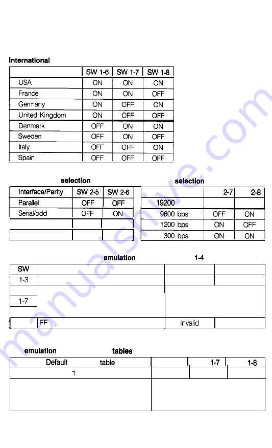
 character set

Country


interface/Parity 

I Serial/even

 ON  OFF 

Serial/none

 ON  ON 

Baud rate 

Baud rate SW 

 SW 

 bps OFF OFF

DIP switch functions in IBM 

 mode 

(DIP switch 

 on)

Description O N

Automatic carriage return ON

l-6

OFF

OFF

Default character table See table below.

l-8

 2-l

   command at the top of form position 

V a l i d

IBM 

 mode character 

 character 

 SW l-6   SW 

  SW 

Table   (standard)

ON

 ON ON

Table 2 (international)

Table 2 is selected when any one
of these switches is turned off.

Summary of Contents for DFX 8000

Page 1: ......

Page 2: ......

Page 3: ...EPSON D F X 8 0 0 0 User s Manual ...

Page 4: ... shall not be liable against any damages or problems arisii from the use of any options or any consumable products other than those designated as Origmal Epson Products or Epson Approved Products by Seiko Epson Corporation All rights reserved No part of this publication may be reproduced stored in a retrieval system or transmitted in any form or by any means mechanical photocopying recording or ot...

Page 5: ...from overheating these openings must not be blocked or covered The openings should never be blocked by placing the product on a bed sofa rug or other similar surface This product should never be placed near or over a radiator or heat register This rdduct should not be placed in a built in instAlation unless proper ventilation is provided This product should be operated from the type of power sourc...

Page 6: ...Remove may expose you to dangerous voltage points or other risks Refer all servicing in those compartments to service personnel 13 Unplug this product from the wall outlet and refer servicing to qualified service personnel under the following conditions A When the power cord or 1 is damaged or frayed B If liquid has been spilled into the product C If the product has been exposed to rain or water D...

Page 7: ...Chapter 2 Paper Handling 2 1 Using the Two Tractor System 2 2 Switching between Front and Rear Tractors 2 20 Changing the Paper 2 24 Printing on Special Paper 2 29 Chapter 3 Using the Printer 3 1 Operating the Control Panel 3 2 Setting the DIP Switches 3 7 Page Length 3 17 Skip Over Perforation 3 18 Using the Paper Memory Feature 3 20 Adjusting the Top of Form Position 3 33 Adjusting the Printing ...

Page 8: ...rinter Options 5 1 Pull Tractor 5 2 Paper Cutter 5 19 Interface Boards 5 32 Chapter 6 Maintenance 6 1 Cleaning the Printer 6 2 Replacing the Ribbon 6 4 Transporting the Printer 6 9 Chapter 7 Troubleshooting 7 1 Problems and Solutions 7 2 Power Supply 7 3 Printing 7 4 Paper Handling 7 13 Options 7 18 Chapter 8 Technical Specifications 8 1 Printer Specifications 8 2 Interface Specifications 8 11 Ini...

Page 9: ...mmand Summary 9 2 Commands in Numerical Order 9 5 Epson ESC P Commands Arranged by Topic 9 9 IBM Emulation Mode Commands Arranged by Topic 9 41 Appendix A l Proportional Width Table A 2 Character Tables A 6 Glossary GL 1 Index IN 1 Contents vii ...

Page 10: ...using the printer This information is necessary for the day to day operation of your printer Chapter 4 provides information on enhancing your printing using software commands and graphics and creating your own user defined characters Chapter 9 contains a summary of printer commands Chapter 7 contains troubleshooting information If the printer does not operate properly or the printed results are no...

Page 11: ...ut the United States Epson America provides product information and support to its dealem and Customer Care Centers Therefore we a that you contact the business where you purchased your Epson product to request assistance If the people there do not have the answer to your question they can obtain it through our dealer support program Epson is confident that this policy will provide you with the as...

Page 12: ... paper quickly and easily The printer remembers separate top of form positions for each tractor An automatic paper back out feature that allows you to switch between paper loaded on the front or rear tractor without removing either paper supply A short tear off feature that saves paper When a sheet of continuous paper is torn off at the end of a printout the printer reverse feeds the remaining pap...

Page 13: ... ESC P commands used by FX 850 1050 and DFX 5000 printers l An IBM emulation mode that provides compatibility with application programs written specifically for IBM printers Options The following options are available for use with your DFX 8000 printer For detailed information on installing and using these options see Chapter 5 l Pull Tractor 4 8309 This option improves the handling of heavy multi...

Page 14: ...y cutting off printed documents for you l Interface Boards You can use several optional interface boards to supplement the printer s built in parallel and serial interfaces Chapter 5 provides guidelines for choosing the right interface and instructions for installing an interface board Introduction 5 ...

Page 15: ...rds Coax and Twinax let you use the DFX 8000 as a local printer fez an IBM mainframe or minicomputer These boards connect directly to the printer and allow it to function as a local IBM printer without the addition of any other circuitry or components 6 Inkduction ...

Page 16: ...r 1 7 Assembling the Printer l 9 Installing the ribbon cartridge l 9 Testing the Printer 1 13 Plugging in the printer 1 13 Running the self test 1 15 Solving any self test problems 1 24 Connecting the Printer to Your Computer l 26 The parallel interface 1 27 The serial interface 1 31 Setting Up Your Application Software l 36 Setting Up the Printer l l ...

Page 17: ...Unpacking the Printer Because the printer weighs approximately 64 lbs 29 kg you should not lift or carry it alone Two people should carry it by the bottom as shown here 1 2 Setting Up the Printer ...

Page 18: ...e sure that you have all the parts shown below and that none have been damaged during transportation power cable optional connector lock nuts ribbon cartridge cross head screwdriver In some locations the power cable may be attached to the printer Setting Up the Printer 1 3 ...

Page 19: ...materials in case you ever need to transport your printer Removing the protective materials The printer is protected during shipping by two brackets a carriage guide support bar and a plastic print head protector Your printer may also be protected by several pieces of foam packaging These protective items must be removed before you turn on the printer After removing the protective materials as des...

Page 20: ...wdriver to remove the five screws and the two transport locking brackets from the inside of the printer 3 Remove the print head protector as shown below Then lift up the paper bail and remove the piece of foam packing underneath it Setting Up the Printer 1 5 ...

Page 21: ...king the Printer 4 Using the enclosed cross head screwdriver remove the carriage guide support bar WARNING Be sure to remove all protective materials before you turn on the printer 1 6 Setting Up the Printer ...

Page 22: ...r plug WARNING Avoid locations that are subject to direct sunlight excessive heat moisture or dust Avoid using electrical outlets that are controlled by wall switches or automatic timers Accidental interruption of power can wipe out information in your computer s and your printer s memory Avoid using outlets on the same circuit with large motors or electrical appliances that might cause fluctuatio...

Page 23: ... angle The printer should always be kept level If you keep your paper supply underneath the printer stand be sure there is enough clearance to prevent the paper from catching on the underside of the stand Also check to see that the distance between the stand supports is wide enough to accommodate the paper you will be using Position your printer s power cable and interface cable so that they do no...

Page 24: ...e ribbon cartridge Before installing the ribbon cartridge make sure that the printer is not plugged into an electrical outlet Remove the ribbon cartridge from its box and plastic wrapper and then follow these steps to install the ribbon cartridge 1 Open the top cover by lifting its front edge up and away from you Setting Up the Printer 1 9 ...

Page 25: ... below 3 Remove the separator from the middle of the ribbon cartridge and discard it Then detach the ribbon guide from the ribbon cartridge but not f r o mthe ribbon and turn the ribbon tightening knob in the direction of the arrow to take up any slack in the ribbon 1 10 setting Up the Printer ...

Page 26: ...down into position until the other two hooks snap into place over the mounting pins in the Note Press lightly on both sides of the cartridge to make sure the hooks are properly connected 5 Insert the ribbon guide over the metal pins on each side of the print head The smaller end of the guide should be on top with its angled edge toward the platen Turn the ribbon tightening knob again to remove any...

Page 27: ...Assembling the Printer 6 Slide the print head from side to side to make sure that it moves smoothly and that the ribbon is not twisted or creased 7 Close the top cover 1 12 Setting Up the Printer ...

Page 28: ... to make sure that your printer was not damaged during shipping and that the ribbon is correctly installed Before performing the self test you need to plug in your printer and load paper Plugging in the printer 1 Make sure that the printer is turned off 2 Check the label on the printer s back panel to make sure the voltage required by the printer matches that of your electrical outlet Setting Up t...

Page 29: ...r cable 3 If necessary connect the power cable to the AC inlet on the printer s rear panel 4 Plug the power cable into a properly grounded electrical outlet 9 WARNING Whenever you turn off the power wait at least five seconds before turning it back on Rapidly switching the power on and off can damage the printer 1 14 Setting Up the Printer ...

Page 30: ...est can be run in draft or Near Letter Quality NLQ mode depending on which button you hold down as you turn on the printer 1 Be sure the printer is turned off 2 Open the front cover by lifting its bottom edge up and toward you Setting Up the Printer 1 15 ...

Page 31: ...the sprocket lock levers on both the right and sprocket units by pulling each lever down left 4 Slide the left sprocket unit all the way to the left Lock it in place by pushing the sprocket lock lever up 1 16 Setting Up the Printer ...

Page 32: ... slide the right sprocket unit to approximately match the width of your paper Do not lock it in place yet 6 Slide the two paper supports so that they are spaced evenly between the two sprocket units Setting Up the Printer 1 17 ...

Page 33: ... sure your paper has a clean straight edge and then fit the first four holes in the paper over the pins of both sprocket units Then close the sprocket covers The side of the paper that you want to print on should be facing you 1 18 Setting Up the Printer ...

Page 34: ...hing the sprocket lock lever up a CAUTION Be sure the sprocket units are not too far apart l If they pull your paper too tightly or if they tear the ed s of the paper holes a paper jam may result To remove any excess tension in your paper release the right sprocket once and lock it again 10 Close the front cover Setting Up the Printer 1 19 ...

Page 35: ...or NLQ mode turn on the printer The POWERa n dPAPER OUT lights come on Also either the front rear tractor arrow on the PAPER SELECT indicate lights up or Notes l When NLQ mode is selected using DIP switch l 5 the self test runs in the NLQ mode even if you press the LINE FEED button l If you open the top cover while the DFX is printing the printer beeps four times goes off line and stops printing T...

Page 36: ...st The ON LINE light does not go on A list of your printer s DIP switch settings is printed first followed by a series of characters The self test continues until the paper runs out or you press the ON LINE button 14 If the test results are satisfactory and you wish to stop the test press the ON LINE button If the test results are not satisfactory see page l 24 for possible causes and solutions No...

Page 37: ...parator cover the back flap of the top cover and tear off the paper at the perforation 16 Turn off the e printer WARNING Whenever you turn off the power wait at least five seconds before turning it back on Rapidly switching the Power on and off candamage the printer 1 22 Setting Up the Printer ...

Page 38: ... e of zern Not slashed CG table SOH OFFH Italic ESC F mode SWl SWl SWl SWl rox 0123456789 IABCDEFGHIJKLMNOP O 0123456789r CBCDEFGHIJKLMNOPOf If 0123456789 ABCWEFGtiIJKLMNOFQR Note Your printer s default setting is high speed draft mode If you want to run the self test in normal draft mode you need to select normal draft mode using DIP Switch2 2 See the section on setting DIP switches in Chapter 3 ...

Page 39: ...e test did not print when you pressed the ON LINE button Turn off the printer remove the jammed paper and then load fresh paper See page l 15 The ribbon cartridge may not be installed properly Turn off the printer and remove the ribbon cartridge Then reinstall it and take up any slack in the ribbon See page 1 9 The ribbon may be worn out Replace the ribbon cartridge See page 6 4 Turn off the print...

Page 40: ... possible See page 6 4 There is either too much slack in the ribbon or the ribbon is caught on something Stop printing turn off the printer and reinstall the ribbon cartridge See page 1 9 The ribbon cartridge may not be installed properly Turn off the printer remove the ribbon cartridge and then reinstall it Make sure the cartridge hooks are inserted securely into the printer See page 1 11 The pri...

Page 41: ...check your computer manual parallel interface serial interface If you have a suitable shielded cable you should be able to connect the printer to most computers immediately If your computer requires another type of interface you need to use an optional interface board See the section on interface boards in Chapter 5 The parallel interface is the printer s default setting If you need to use the bui...

Page 42: ...lel interface Follow these steps to connect the parallel interface cable to the printer 1 Turn off both the printer and computer 2 Open the rear cover by grasping it by the handholds on each side and pulling it out and down Setting Up the Printer 1 27 ...

Page 43: ... into the parallel interface the socket on the left WARNING Do not plug more than one interface cable into the printer at one time This may damage the printer 4 Squeeze the wire clips together until they lock in place on either side of the connector 1 28 Setting Up the Printer ...

Page 44: ...e has a ground wire connect it to the Pnter s ground connector 6 Open the plastic clamp to the right of the parallel and serial interfaces by pressing down on its top tab Insert the cable in the plastic clamp and close the clamp Setting Up the Printer 1 29 ...

Page 45: ...r CAUTION Always close the rear cover before using the printer 8 Plug the other end of the cable into the computer If there is a ground wire at the computer end of the cable attach it to the ground connector at the back of the computer 1 30 Setting Up the Printer ...

Page 46: ...ial interface Follow these steps to connect the serial interface cable to the printer 1 Turn off both the printer and computer 2 Open the rear cover by grasping it by the handholds on each side and pulling it out and down Setting Up the Printer 1 31 ...

Page 47: ...rial interface the socket on the right WARNING Do not plug more than one interface cable into the printer at one time This may damage the printer 4 If your cable connector has screws that you need to tighten using a screwdriver open the top cover of the printer 1 32 Setting Up the Printer ...

Page 48: ...rear paper guide and fasten the screws of the cable connector Note If the screws that come with the cable do not fit into the connector lock nuts on the interface replace the lock nuts with the optional lock nuts provided with the printer 6 Close the top cover Setting Up the Printer 1 33 ...

Page 49: ... has a ground wire connect it to the printer s ground connector 8 Open the plastic clamp to the right of the parallel and serial interfaces by pressing down on its top tab Insert the cable in the plastic clamp and close the clamp l 34 Setting Up the Printer ...

Page 50: ... CAUTION Always close the rear cover before using the printer 10 Plug the other end of the cable into the computer If there is a ground wire at the computer end of the cable attach it to the ground connector at the back of the computer Setting Up the Printer 1 35 ...

Page 51: ... installation or setup procedure that lets you select your printer from a list of printers choose the Epson DFX 8000 printer If the list does not include the DFX 8000 choose one of the following printers listed in order of preference DFX 5000 FX 1050 FX 850 FX 286e FX 86e Ex l000 EX 800 FX 185 FX 85 FX lOO FX 80 FX 100 FX 80 If these printers are not listed select one of the following printers lis...

Page 52: ...n order of preference IBM Proprinter XL IBM Graphics printer IBM Printer Note To use all the features of the DFX 8000 it is best to use a program with the DFX 8000 on its menu If your software program does not list the DFX 8000 contact the software manufacturer to see if an update is available Setting Up the Printer 1 37 ...

Page 53: ...r supply 2 2 Loading paper onto the front tractor 2 4 Loading paper onto the rear tractor 2 11 Switching between Front and Rear Tractors 2 20 Changing the paper 2 24 Printing on Special Paper 2 29 Copy mode 2 29 Multi part forms 2 30 Labels s 2 32 P a p e r Handling 2 l ...

Page 54: ...es of paper it is best to load the paper you use most often onto the rear tractor That way you can use the front tractor which is easier to reach for paper you change more often Positioning the paper supply Since the DFX 8000 can be loaded with continuous paper from both the front and the rear be sure to leave enough room around the printer for two stacks of fresh paper and a third stack of printe...

Page 55: ... of printed pages does not interfere with the rear tractor s paper supply front loaded paper rear loaded paper CAUTION Be sure your printed output folds properly as it comes out of the printer It should fold at the perforation between pages P a p e r Handling 2 3 ...

Page 56: ...o Tractor System Loading paper onto the front tractor The foIlowing steps show you how to load paper onto the front tractor 1 Turn off the printer 2 Open the front cover by lifting its bottom edge up and toward you ...

Page 57: ...lease the sprocket lock levers on both the right and left sprocket units by pulling each lever down 4 Slide the left sprocket unit all the way to the left Lock it in place by pushing the sprocket lock lever up P a p e r Handling 2 5 ...

Page 58: ...tem 5 Now slide the right sprocket unit to approximately match the width of your paper Do not lock it in place yet 6 Slide the two paper supports so that they are spaced evenly between the two sprocket units 2 6 Paper Handling ...

Page 59: ...four holes in the paper over the pins of both sprocket units The side of the paper that you want to print on should be facing you Then close the sprocket covers CAUTION Make sure your paper has a clean straight edge before inserting it into the printer P a p e r Handling 2 7 ...

Page 60: ... the sprocket lock lever up CAUTION Be sure the sprocket units are not too far apart If they pull your paper too tightly or tear the edges of the paper holes a paper jam may result To remove any excess tension in your paper release the right sprocket and lock it again 10 Close the front cover The paper is now loaded to the standby position 2 8 Paper Handling ...

Page 61: ...ar tractor arrow on the PAPER SELECT indicator lights up depending on which tractor was selected when the printer was turned off last 12 Check the PAPER SELECT indicator to see which tractor is s e l e c t e d l If the front tractor arrow is lit up press the LINE FEED LOAD button to load the paper Paper Handling 2 9 ...

Page 62: ...actor When the printer switches tractors it also loads the paper automatically 13 Press the ON LINE button to put the printer on line so it is ready to print The paper is now loaded to the top of form position If it looks like the printing will start too high or low on the page see the section on adjusting the top of form position in Chapter 3 2 10 Paper Handling ...

Page 63: ... Cha qr 3 l If you open the top cover while the DFX is printing the printer beeps four times goes off line and stops printing To resume printing close the top cover and press the ON LINE button Loading paper onto the rear tractor The following steps show you how to load paper onto the rear tractor You can load paper onto the rear tractor without removing the paper from the front tractor 1 Turn off...

Page 64: ...Using the Two Tractor System 2 Open the top cover by lifting its front edge up and away from you 3 Open the rear flap at the back of the top cover 2 12 Paper Handling ...

Page 65: ... printer release the sprocket lock levers on the rear tractor s right and left sprocket units by Pushing each lever back 5 Slide the left sprocket unit all the way to the left Lock it in place by pulling the sprocket lock lever forward Paper Handling 2 13 ...

Page 66: ...tem 6 Now slide the right sprocket unit to approximately match the width of your paper Do not lock it in place yet 7 Slide the two paper supports so that they are spaced evenly between the two sprocket units 2 14 Paper Handling ...

Page 67: ...t to print on facing down insert the paper through the opening at the rear of the printer You may find it easier to load the paper by standing to the side of the printer That way you can feed the paper through the rear opening with one hand and pull it through with the other Paper Handling 2 15 ...

Page 68: ...nto the printer 10 Fit the first four holes in the paper over the pins of the sprocket units Then close the sprocket covers 11 Slide the right sprocket unit so that the paper is straight and has no wrinkles Then lock the sprocket unit in place by pulling the sprocket lock lever forward 2 16 Paper Handling ...

Page 69: ...ess tension in your paper release the right sprocket and lock it again 12 Close the top cover and the rear flap The paper is now loaded to the standby position 13 Turn on the printer The POWER and PAPER OUT lights go on Also either the front or rear tractor arrow on the PAPER SELECT indicator lights up depending on which tractor was selected when the printer was turned off last Paper Handling 2 17...

Page 70: ...e rear tractor arrow is lit up press the LINE FEED LOAD button to load the paper l If the front tractor arrow is lit up make sure the printer is off line and then press the FRONT REAR button to switch to the rear tractor When the printer switches tractors it also loads the paper automatically ha 2 18 Paper Handling ...

Page 71: ...ing the top of form position in Chapter 3 Notes l Before you begin printing be sure to check the page length and skip over perforation settings and readjust the settings if necessary See the section on page length and skip over perforation in Chapter 3 l If you open the top cover while the DFX is printing the printer beeps four times goes off line and stops printing To resume printing close the to...

Page 72: ...switch between tractors when labels are loaded in the printer or a paper jam may result Instead completely remove the labels first by tearing off the fresh supply below the tractor and pressing the FORM FEED or LINE FEED button to eject the remaining labels Before you start make sure the printer is turned on and that the front tractor is selected The front tractor arrow on the PAPER SELECT indicat...

Page 73: ... on loading paper onto the rear tractor in this chapter for instructions Open the paper separator cover at the back of the top cover If you have a printed document still in the printer OF excess paper that has been fed through the printer use the short tear off feature de d in Chapter 3 to tear off the document or excess paper Paper Handling 2 21 ...

Page 74: ...ore switching tractors Never feed more than one page backward 5 Close the paper separator cover 6 Make sure the top cover is closed and then press the FRONT REAR button to switch to the rear tractor The printer feeds the front loaded paper back to the standby position and advances the rear loaded paper to the top of form position 2 22 Paper Handling ...

Page 75: ...button to put the printer on line so it is ready to print Note If you open the top cover while the DFX is printing the printer beeps four times goes off line and stops printing To resume printing close the top cover and press the ON LINE button Paper Handling 2 23 ...

Page 76: ...the paper on the rear tractor the rear tractor should be selected instead I 9 WARNING Never change paper using the following procedure if labels are already loaded in the printer Instead completely remove the labels first by tearing off the fresh supply below the tractor and pressing the FORM FEED or LINE FEED button to eject the remaining labels Then load new paper as described in this chapter 1 ...

Page 77: ...ss paper WARNING Always tear off printed documents before WARNING Always tear off printed documents before changing the paper Never feed more than one page changing the paper Never feed more than one page backward through the printer backward through the printer 3 Press the FRONT REAR button to switch to the rear tractor The front loaded paper automatically feeds back to the standby position Paper...

Page 78: ...Changing the Paper 4 Open the front cover To change the rear loaded paper open the top cover and the rear flap 5 Open the sprocket covers and remove the paper from the tractor 2 26 Paper Handling ...

Page 79: ...s described in the section on loading paper onto the front tractor in this chapter If you are loading paper onto the rear tractor see the section on loading paper onto that tractor 7 Close the front cover or close the top cover and the rear flap Paper Handling 2 27 ...

Page 80: ...the top of form position Then press the ON LINE button to put the printer on line so it is ready to print Note If you open the top cover while the DFX is printing the printer beeps four times goes off line and stops printing To resume printing close the top cover and press the ON LINE button 2 28 Paper Handling ...

Page 81: ...e length in Chapter 3 If you are using labels or preprinted or multi part forms you may want to use the optional pull tractor See Chapter 5 WARNING When printing on multi part forms or labels make sure that your printing stays within the printable area of the paper to prevent damage to the print head For more information on the printable area see page 8 6 Copy mode If the printing on the last page...

Page 82: ... forms that meet the requirements listed in the section on paper in Chapter 8 WARNING Never use multi part forms thst have metal s t a p l e s You load continuous multi part forms the same way as you load any other type of continuous paper Before loading multi part forms make sure that the paper has a clean straight edge and does not separate or tear apart See the sections on loading paper earlier...

Page 83: ...bel area and in the places where they overlap and are joined together as shown below overlapping multi part forms multi part forms with labels 0 t CAUTION Be sure to use the paper memory feature before l you print on multi part forms that vary in thickness See Chapter 3 for instructions When you print on these forms make sure that the printing fits within the printable area and the top of form pos...

Page 84: ...abels backward through the printer you can still use the DFX 8000 s automatic paper handling features if you follow these precautions Instead of using the TEAR OFF button to remove printed labels take the printer off line and press the FORM FEED or LINE FEED button until the last printed label is at the point where you can tear it off easily Before using the FRONT REAR button to itch tractors or c...

Page 85: ...mber of labels print only one page of labels to make sure all the text is printed within the label area WARNING Since labels are especially sensitive to extreme temperature and humidity always use them under normal operating conditions Paper Handling 2 33 ...

Page 86: ... Perforation 3 18 Using the Paper Memory Feature 3 20 Saving paper format and thickness information 3 21 Loading paper format from memory 3 31 Adjusting the Top of Form Position 3 33 Adjusting the Printing Position 3 37 Using Short Tear Off 3 40 Selecting Typestyles 3 43 Character fonts 3 43 Character spacing 3 45 Condensed mode 3 46 Selecting an International Character Set 3 47 Choosing a Charact...

Page 87: ...h tractor is ready to print The following sections describe the functions of the control panel s lights and buttons The indicator lights on the control panel let you check the current status of the printer Below is an illustration of the control panel lights and a description of their functions Lights POWER green On when the power switch is on and power is supplied to the printer READY green On wh...

Page 88: ...light blinks The printer stops printing waits several minutes while the print head cools and then resumes printing TEAR OFF green On when the printer is in tear off mode TOP OF FORM green On when the printer is in top of form mode tvhen this light blinks you can adjust the loading and top of form positions PAPER SELECT red green The front tractor arrow goes on when the front tractor is selected Th...

Page 89: ...the computer When the printer is in top of form mode you can press the ON LINE button to exit the mode without setting a new top of form position You can Also press the ON LINE button to it tear off mode See the sections on adjtisting the top of form position and using short tear off in this chapter FORM FEED COPY When the printer is off line press this button to advance the paper to the top of th...

Page 90: ...ear off edge you can use the MICRO FEED buttons to adjust the tear off position See the section on using short tear off in this chapter WARNING Never use the TEAR OFF button with labels Press the FORM FEED or LINE FEED button instead to feed the printed labels to a point where you can tear them off MICRO FEED When the printer is off line the two MICRO FEED buttons advance or reverse the loaded pap...

Page 91: ... check whether your printer operates properly The self test prints the current DIP switch settings a n dthe characters in the printer s ROM Read Only Memory Your printer offers both draft and NLQ self tests To start the self test hold down the LINE FEED or FORM FEED button and turn on the printer See the section on running the self test in Chapter l for more information Data dump To enter data dum...

Page 92: ...describe the functions of the DIP switches Because the factory default settings are 9 igned to accommodate the needs of most users you probably MM t change DIP switch settings very often WAenyoudo need to t a DIP switch follow the steps below Be sure to turn off the printer before you start and turn it on again when you are done Neti DIP switch settings take effect only after you tum on or reset t...

Page 93: ...Setting the DIP Switches 2 Open the front cover If there is paper loaded on the front tractor remove it 3 Open the DIP switch cover as shown below 3 8 Using the Printer ...

Page 94: ...h as the tip of a pen or pencil to turn a switch on or off A DIP switch is on when it is up and off when it is down CAUTION Always make sure the printer is turned off before you change the DIP switch setti 5 Close the DIP switch cover Using the Printer 3 9 ...

Page 95: ...ings take effect when you turn on the printer The DIP switch tables The tables on the next page describe the functions of the DIP switches The shaded boxes show the default or factory settings See the page numbers listed on the right for more information about each feature 3 10 Using the Printer ...

Page 96: ...2 7 Baud rate See e table on 2 8 page 3 13 3 16 l The default setting for DIP switch l 3 varies depending on the country When DIP switch 1 4 is on and the printer is in IBM emulation mode the functions of DIP switches 1 3 1 6 1 7 1 8 and 2 1 differ from those listed in this table See the table on page 3 13 for their functions in IBM emulation mode Using the Printer 3 11 ...

Page 97: ... oat t forms Multi part forms with labels Skip over binding Handshaking protocol ON Memory 2 Valid Valid ON X on X f l The default setting for DIP switch 3 2 varies depending on the country International character set 3 18 I 3 20 1 3 16 1 I 3 16 The default settings for these DIP switches vary depending on the country 3 12 Using the Printer ...

Page 98: ...ulation mode DIP switch functions in IBM emulation mode SW Q8scriptiin ON OFF 1 3 Automatic cafriaae return OFF ON 1 6 1 7 1 8 2 1 Default character table See table below FF command at the top of form position Invalid Valid IBM emulation mode character tables Default character table SW l 6 SW 1 7 SW 1 8 Table 1 l O N O N O N Table 2 Table 2 is selected when any one of these switches is turned off ...

Page 99: ...itches in IBM emulation mode Default character set When DIP switch 2 l is on the user defined character set is the default User defined characters are maintained in the printer s memory even when the power is turned off so you can select the user defined character set simply by turning on this DIP switch However when the switch is on you cannot define new user defined characters The setting of thi...

Page 100: ...ts When the DIP switch is off the bit length is set to 8 bits Auto line feed When DIP switch 2 4 is on the printer adds a line feed LF command to every carriage return CR code sent by the application program When the switch is off line feeds occur only when the software sends line feed commands to the printer Since most computers and application programs automatically add line feeds to carriage re...

Page 101: ...ect baud rate setting Your computer and printer should always be set to the same baud rate Input buffer The printer s input buffer provides additional memory to free up the computer while you print large amounts of text or graphics The input buffer is enabled when DIP switch 3 1 is off To disable the buffer turn on DIP switch 3 1 Skip over binding When DIP switch 3 7 is on the print head avoids th...

Page 102: ... is on the page length is 12 inches 30 48 cm Be sure to set the page lenth to match the paper you plan to use Other page lengths can be set with the ESC C and ESC CO commands See the Command Summary in Chapter 9 11 inch page length DPswitch 2off 1Pinch page length DIP switch 3 2 on Using the Printer 3 17 ...

Page 103: ...tion off DIP switch 3 3 off l 0123456789 ABCDEFGHIJKLMNOPQRSTU 123456789 ABCDEFGHIJKLMNOPQRSTW 23456789 c ABCDEFGBIJKI lNQPQRSTWW 3456 789 ABCDEFGHI JKDMHQPQRSTWWX i 456789 DEFGHI KLMNOPGRSTWWXY c 56789 F z D md mPmmm z l 6789 QABCDEFGHIJK MNOPQRSTWWXYZC 789 ABCDEFGHIJKL NOPQRSTWWXYZ 89 ABCDEFGHIJKLMMOPQRSTWWXYZC l l Q ABCDEFGHIJKLMNQPQRSTWbMYZ l skip over perforation on DIP switch 3 3 on l 012345...

Page 104: ...Skip Over Perforation insert their own top over perforation feature only if your program does not provide them Using the Printer 3 19 ...

Page 105: ...glued together Examples of these forms are shown below overlapping multi multi part forms part forms with labels You can save paper format and thickness information for up to two multi part forms on the printer s paper memory areas When you tell the printer it is using a certain form the printer automatically adjusts the gap between the print head and the platen to provide maximum printing quality...

Page 106: ...w to set a DIP switch Saving paper format and thickness information The following sections describe how to save paper format and thickness information for different types of multi part forms Saving information for overlapping multi part forms To save paper format and thickness information for multi part forms that overlap slightly where they are joined together follow the steps below 1 Turn off th...

Page 107: ...age length after you finish saving the overlapping form information Page length DIP SW 3 2 11 inches OFF 12 inches I ON I 4 Turn on DIP switch 3 5 and turn off DIP switch 3 6 This tells the printer you want to save information for multi part forms that overlap slightly where they are joined together Note Whenever DIP switch 3 5 is on the skip over perforation feature is valid regardless of DIP swi...

Page 108: ...eps and goes off line You can print on these forms even if you turn the printer off and then back on To use other types of paper see the section on loading paper format information from memory later in this chapter CAUTION When you print on these forms make sure that the printing fits within the printable area and the top of form position is set properly The printable area is shown in Chapter 8 Us...

Page 109: ...rea where you want the printer to store the paper format and thickness information Memory area 1 is selected when DIP switch 3 4 is off This is the printer s default setting To select memory area 2 turn on the switch Paper memory DIP SW 3 4 Memory 1 OFF Memory 2 ON Use DIP switch 3 2 to set the page length If you plan to use forms of a different page length use software commands to set the page le...

Page 110: ...INE FEED LOAD button to load the forms The printer loads and checks the forms When the check is finished the printer beeps continuously until you open the top cover in the next step CAUTION Do not go on to the next step before the printer beeps to tell you the check is finished 7 Open the top cover Using the Printer 3 25 ...

Page 111: ...ons to adjust your paper s position so that the top edge of the label is aligned with the horizontal red line on the clear plastic ribbon mask 9 Move the print head by hand to align the vertical red line on the ribbon mask with the left edge of the label Now the intersection of the red lines on the ribbon mask should be in the upper left comer of the label 3 26 Using the Printer ...

Page 112: ... TOP OF FORM button The printer beeps once 0 TOP OF VORM 11 Use the MICRO FEED buttons to adjust your paper s posftion so that the bottom edge of the label is aligned with the horizontal red line on the ribbon mask h FEED Using the Printer 3 27 ...

Page 113: ...hould be in the lower right comer of the label 13 Press the TOP OF FORM button The printer beeps twice This tells the printer the label s location on the form a TOP OF FORM Note If the label s location is still not correct repeat the above procedure from step 8 on page 3 26 Be sure that you set both the upper left and lower right comers of the label when performing this procedure 3 28 Using the Pr...

Page 114: ...ow an error has occurred In step 14 the printer advances the form one page according to the setting of DIP switch 3 2 If your form has a different page length set the correct page length with software commands and adjust the top of form position accordingly You can print on these forms even if you turn the printer off and then back on To use other types of paper see the section on loading paper fo...

Page 115: ...s selected when DIP switch 3 4 is off This is the printer s default setting To select memory area 2 turn on the switch Use DIP switch 3 2 to set the page length The page length is 11 inches when DIP switch 3 2 is off and 12 inches when the switch is on If you plan to use forms of a different page length use software commands to set the page length after you finish saving the form s information Tur...

Page 116: ...aper memory feature the printer loads your form s information from its memory To select the paper memory feature follow the steps below 1 Load the multi part forms you want to use onto the front tractor 2 Turn off the printer 3 Now load the paper format and thickness information for the multi part forms you want to use To load the information from memory area 1 hold down the top MICRO FEED button ...

Page 117: ...ses this information as the default setting when you turn on the printer To use regular continuous paper after using multi part forms that vary in thickness hold down the FRONT REAR button and turn on the printer CAUTION While the paper memory feature is selected and your multi part form s format and thickness information is loaded do not use other types of paper 3 32 Using the Printer ...

Page 118: ...inting position in the middle of a page as described in the next section The printer remembers the temporary top of form position until the next time you load paper or switch tractors You can set the top of form position from 0 1 inches 2 6 mm to 22 inches 558 8 mm below the top edge of paper The factory setting is the 0 2 inches 5 8 mm position below the top edge of paper I 9 WARNING When labels ...

Page 119: ...FORM button to enter top of form mode The printer beeps the TOP OF FORM light goes on and the printer advances the paper slightly CAUTION Whenever you press the TOP OF FORM button and the TOP OF FORM light goes on the printer sets a new top of form position If you press the TOP OF FORM button by mistake you can press the ON LINE button to cancel the new setting and exit top of form mode 3 34 Using...

Page 120: ...xt will actually be printed five lines below the top of form position Using the red line as a reference press the MICRO FEED buttons to feed the paper to the desired top of form position Press the top or bottom MICRO RED button once to feed the paper forward or backward 1 216th of an inch or hold down the button to move the paper continuously FEED Note The red line on the ribbon mask shows you whe...

Page 121: ... position If you want to exit top of form mode without saving your new top of form setting press the ON LINE button instead of the TOP OF FORM button Close the top cover 6 Press the ON LINE button to put the printer on line Note If you enter top of form mode right after loading paper the TOP OF FORM light blinks While the TOP OF FORM light is blinking you can set the loading and top of form positi...

Page 122: ...ing position you temporarily change the top of form position by the same amount For example if you adjust the printing in the middle of a page so that it falls a half inch lower the next page also begins a half inch lower The printer remembers this temporary top of form position until the next time you switch tractors or load paper 1 Press the ON LINE button to take the printer off line Using the ...

Page 123: ... top or bottom MICRO FEED button once to feed the paper forward or backward 1 216th of an inch or hold down the button to move the paper continuously MICRO FEED WARNING If you are using labels use only the forward feeding top MICRO FEED button 3 38 Using the Printer ...

Page 124: ...Adjusting the Printing Position 4 When you are finished close the top cover and press the ON LINE button to put the printer on line Using the Printer 3 39 ...

Page 125: ... perforation so that it meets the printer s tear off edge if you need to If you set a new tear off position the printer remembers the new setting even after the printer is turned off reset or initialized The printer remembers separate tear off positions for front and rear tractors I WARNING Never use the TEAR OFF button with labels or when the optional pull tractor is installed 1 Make sure that th...

Page 126: ...erforation so that it meets the printer s tear off edge use the MICRO FEED buttons You can press the top or bottom MICRO FEED button once to feed the paper forward or backward l 216 of an down the button to feed the paper continuously inch or hold Note You can reset the tear off position only when you are in tear off mode after you have pressed the TEAR OFF button once and the TEAR OFF light is on...

Page 127: ...ion Then press the O N LINE button to put the printer on line so it is ready to print Or instead just press the ON LINE button to feed the paper back and put your printer on line at the same time WARNING Always tear off the printed document before you feed the paper back to the top of form position Never feed paper backward more than one page 1 3 42 Using the Printer ...

Page 128: ... font turn off DIP switch 1 5 TheDFX 8000 can print the draft font at two speeds The draft font printing speed is high when DIP switch 2 2 is off and normal when the switch is on NLQ mode produces high quality text characters at a slower printing speed The DFX 8000 offers two NLQ fonts Roman and Sans Serif To select NLQ mode turn on DIP switch 1 5 In Epson ESC P mode which is selected when DIP swi...

Page 129: ... one gross NLQ Roman 0123456789 ABCI FGHIJK LMN0PQRSTWWXYZC l abcdefghijklmnopqmtuv WXYZC I We ve just seen your excellent ad for miniature aebrga in a recent back issue of Timee What is the price schedule fob quantities over one prom NLQ Sans Serif b I 0123456789 QBCDEFGHIJK LMNOPQRSTUVWXYZC rbcdefghijklmnopqrstuv wxyzc 1 We ve just seen your excellent ad for miniature zebras in a recent back iss...

Page 130: ...r gets an equal amount of space In proportional mode the spacing varies from character to character A narrow letter like the lowercase i receives less space than the uppercase W The printout below compares the different types of spacing 10 cpi T h i s i s 10 CPI p r i n t i n g ABCDEFGHIJKLMNOPQRSTWWKYZ abcdefghijklmnopqrstuvwxyz 12 cpi This is 12 CPI printing ABCDEFGHIJKL lt OmZ abodefghi jklmnop...

Page 131: ...ere you need to print the maximum amount of information on a page Both 10 and 12 cpi printing can be condensed but proportional printing cannot To select condensed mode turn on DIP switch l l The printout below compares normal 10 and 12 cpi printing with condensed 10 and 12 cpi printing T h i s i s 10 cpi p r i n t i n g This is condensed 10 cpi printin This is 12 cpi printing This is condmed 12 c...

Page 132: ...FF OFF International character sets provide you with the characters and symbols used in other languages In Epson ESC P mode which is selected when DIP switch l 4 is off you can select one of eight international character sets by setting DIP switches l 6 l 7 and 1 8 according to the tabIe below The table also shows the characters that differ in each international character set CAUTION Always be sur...

Page 133: ...3 24 40 5B 5C 5D 5E 60 7B 7C 7D 7E 5 Japan cYl cI 9 Norway nBBBAU6zsrabU 10 Denmark II 810AU6aabQ 11 Spain II bifi 6 iA66 12 Latin America 6 i f4JL6tiifi6ti Two character sets are available in IBM emulation mode which is selected when DIP switch l 4 is on The Appendix shows these character sets To select the character set with international characters character set 2 turn off DIP switch 1 6 1 7 or...

Page 134: ...l print text when the Epson Extended Graphics table is selected Also with the proper software commands you can print italics or graphics characters no matter which character table you select See the Command Summary in Chapter 9 Although most software programs work better with the graphics table some programs require the italics table Try switching tables if you have trouble printing lines and othe...

Page 135: ...e printer to initialize the new settings Notes l The ESC 6 command tells the printer to print hex codes 80 to 9F and FF as characters and the ESC 7 command tells the printer to use these hex codes as control codes See the Command Summary in Chapter 9 l In IBM emulation mode which is selected when DIP switch l 4 is on DIP switch 1 3 is used to select or cancel the auto line feed feature information...

Page 136: ... an exact printout of the codes reaching the printer is produced To use data dump mode follow these steps 1 Make sure that paper is loaded You can use the built in tractor units or the optional pull tractor for printing in data dump mode If the printer is on turn it off 2 To enter data dump mode hold down the FORM FEED and LINE FEED buttons and turn on the printer Using the Printer 3 51 ...

Page 137: ...S 74 6F 76 74 2P 20 54 66 Imp printout Th 0004 69 73 20 69 73 20 66 66 61 74 76 72 65 20 6D 61 is is feature ma 0005 6B 65 73 20 69 74 20 65 61 73 79 20 60 6F 72 20 kw it easy for 4 Toturn off data dump mode press the ON LINE button to take the printer off line and then turn off the printer Look at the data dump shown in step 3 By comparing the characters printed in the right column with the print...

Page 138: ...eck the second line of the right column and you will find the letter T preceded by two spaces The chart below interprets the first six nonprintable codes 1 Hex codes Command 1B 40 ESC 1B 52 00 ESC R 0 1B 74 01 ESC t 1 1B 36 ESC 6 12 DC2 1B 50 ESC P Function Initialize printer Select USA character set Select Epson Extended Graphics character table Enable printable characters Cancel condensed mode S...

Page 139: ...1 The graphics commands 4 13 Column reservation numbers 4 14 Printing simple patterns 4 14 Printing taller patterns 4 16 Designing your own graphics 4 17 Individual graphics commands 4 20 The reassignment command 4 20 User defined Characters 4 22 Designing your characters 4 23 Sending information to your printer 4 24 Printing user defined characters 4 26 Copy ROM characters to RAM 4 27 Mixing prin...

Page 140: ...u can make to printing on the DFX 8000 are in the print quality and fonts The DFX 8000 has three levels of print quality high speed draft normal draft and NLQ Near Letter Quality High speed draft is ideal for rough drafts and large documents or reports that you need to print quickly Normal draft is a bit slower but offers higher resolution characters Finally NLQ takes a little longer but produces ...

Page 141: ...dd greater variety to your documents the DFX 8000 has two fixed character spacings and proportional spacing Each one can be selected with a software command For two of the built in fonts normal draft and NLQ you can choose a character spacing of 10 cpi characters per inch 12 cpi or proportional spacing The printout below compares the two types of character spacing T h i s i s 10 cpi p r i n t i n ...

Page 142: ...ble wide mode doubles the width of any size characters while the double high mode doubles the height of any size characters These modes are useful for emphasizing headings in reports and making displays but are usually not suitable for large amounts of text These modes can also be combined to obtain even more impressive printing results T h i s i s n o r m a l 10 cpi p r i n t i n g ThiS i s doubl...

Page 143: ...d by normal draft W ning or narrowing the characters also widens or narrows the space between words and letters Because word processors usually create a left margin by printing spaces you may need to change the number of characters on a line to keep the margins correct if you change widths special efkcta and emphasis The DFX 8000 offers two ways of emphasizing parts of your text and also allows yo...

Page 144: ... fully formed characters In double strike mode the print head goes over each line twice making the text bolder For even greater boldness you can combine emphasized and double strike While NLQ is in use however double strike is ignored because NLQ characters are already formed by two passes of the print head T h i s i s normal draft printing This is emphasized draft printing This is double strike i...

Page 145: ...ke advantage of this feature but some programs use the underline character stead If this happens check your prqqam for an underlining optiori jR cn Superscripts and subscripts Superscripts and subscripts can be used for printing footnote numbers and mathematical formulas The example below shows underlining and subscripts combined in a mathematical formula a v e r a g e L I a 2 n l n Software and G...

Page 146: ...n sending ESCape codes to your printer see Chapter 9 The format of the Master Select code is shown below ASCII ESC n Decimal 27 33 n Hexadecimal 1B 21 n The variable n is a number that identifies the typestyle or combination To find the value of n refer to the table below and add up either the decimal or hexadecimal numbers for the features you want Feature Dec Hex 10 cpi 0 00 12 cpi 1 01 proporti...

Page 147: ...r Select and must be set separately using the ESC x and ESC k commands The draft font printing speed must be set using DIP switch 2 2 See the section on setting DIP switches in Chapter 3 There are four more things to cons er when using the Master Select command Master Select cancels any of th list f u es that you do not set For example if you have eadjl W 2 cpi and you try to use Master Select to ...

Page 148: ...nstructions The quickest and easiest way to print graphics on your printer is to use a commercial graphics program With such a program you usually create an image on your monitor and then give a command to send the image to the printer If you use commercial software that produces graphics all you need to know about dot graph is how to use the software If on the other hand you wish to do your own p...

Page 149: ... inch horizontally and 72 dots vertically The images printed by the printer can therefore be as finely detailed as the one on page 4 10 In its main aphics mode ydur prir tiiints one co of dots for each code it receives and it uses only the top eight of the nine pins Therefore your graphics program muat send codes for dot patterns one numb for each colurnn in a line l o r each o hose columns the pr...

Page 150: ...u send its number To fire more than one p in at tktim time add p the nurtilk of the pins and send the sum to the pfiter VVW tl esc 1 4 r the piA you fin the iop pin by sending 128 To fire the b ttoti pin yoti M l l If you want to irq only the top qnd bott m pins you siq pb d 128 and I and send 129 By addii the appropriate label numbers together you dan fire any com Aation C U Mow are thrke extipld...

Page 151: ...t t turps qn thq graphics mode Jso qpeqifies how many columns of grap F l be p nted After prinW v s this command it interprets the numbers which follow as pin patterns and p d tha f I 1 8 Your pri w hv QJJC I at allows yoi to use angr of the eight graphics options The format of the command is ESC mnltidata In this command m selects the gaqphics option andin and specify the mm r of r mns to reserve...

Page 152: ...ns of gr phica data nl should be 96 andn2shouldbebl rusel632 6 x 256 If you are using a programming language with MOD modulus and INT integer functions you can use the following formulas to calculitte rr2 title in tiki ti is the tad iitixW 9 columns nl nMOD256 I2 INT n 256 The print will i rpre f the ntimber of by det ed by nl and n2 as grapWs data no titter i at codes liey are This means that you...

Page 153: ... and line 50 finishes the loop Note Some software programs including most versions of BASIC automatically insert carriage return and line feed codes after every 80 or 130 characters This is usually no problem with text but it can spoil your graphics Two extra cohnnns of graphics are printed in the middle of the ones you send and two data numbers are left over and printed as text In some versions o...

Page 154: ... S 120 FOR R l TO 6 130 LPRINT CHR 27 K CHR lOO CHR O 140 FOR X l TO 50 150 LPRINT CHR 170 CHR 85 160 NEXT X LPRINT 170 NEXT R 180 LPRINT CHR 27 0 If you rtm the program you will see bow it combines six print lines into a pattern There are five basic steps that the program goes through to produce this kind of pa te 1 The computer is prevented from adding any extra characters by the WIDTH statement...

Page 155: ...e in effect for only one print line To print more than one line of graphics the graphics command must be isiniisd b fore ea line Desigming your owe graphics This section takes you through the development of a graphics program The example here is not especially complicated but it does include the ye steps you would use for a more complex figure First you mug ide which graphics density you want The ...

Page 156: ...ign your fiie by plotting dots on graph paper The high speed double density design shown below should point you in the right direction for your own work After plotting the dots on a g l you calculate thenumbers for each pin pattern by dividing the design grid into separate print lines For the arrow design the grid was divided into two lines each seven dots high Then each column was examined to cal...

Page 157: ...petitive each column of graphics data is read from the DATA statements and sent to the printer The design is 41 dot positions wide therefore both lines 130 and 140 use the number 41 100 WIDTH LPT1 255 110 LPRINT CIiR 27 A CIIR 7 120 FOR ROW 1 TO 2 130 LPRINT CHR 27 Y CHR 41 CHR O 140 FOR COLDMN 1 TO 41 150 READ N 160 LPRINT CHR N 170 NEXT COLUMN 180 LPRINT 190 NEXT ROW 200 END 210 DATA 64 32 80 8 ...

Page 158: ...e that these c ttri ds contam one s variable than the ESC A command because they do not need to select a graphics option I They irie shown below I Command ESC K ESC L ESC Y ESC Z Function Single density Double density Double density high speed Quadruple density ESC Format ESC 0 ESC 1 ESC 2 ESC 3 The reassignment command The DFX 8000 has a command that allows you to change the graphics option assig...

Page 159: ...tion that you want to assign I it For example to w the ESC K command to use the CRT I graphics option the command in BASIC is LPRINT CHR 27 X CHR Q This is a quick way to change the aspect ratio of the design that you are printing Cha ing the graphics option will change the width without changing the height Software and Graphics 4 21 ...

Page 160: ...ets of characters already created Also some popular commercial software programs take advantage of the printer s userdefined character function to enhance printouts These characters are called download characters in some programs The standard characters are stored in the printer s Read Only Memory ROM and the user defined characters are stored in the printer s Random Access Memory RAM In Epson ESU...

Page 161: ...s three of these grids Most characters do not use the two rows below the heavy line Those rows are only for characters with descenders like y and g Also even though you can use up to 11 columns it is best to leave the last two blank for the space between characters 128 64 32 16 8 4 2 1 123456789 123456789 123456789 128 64 32 16 8 4 2 1 L i i i i I 128 64 32 16 8 4 2 1 The grid in the middle shows ...

Page 162: ...ode for a space You can also use other codes by using the ESC 6 and ESC I commands See the Command Summary in Chapter 9 For example if you wanted to redefine the characters A through Z n7 would be A or ASCII code 65 and n2 would be Z or ASCII code 90 So the command ESC h 0 AZ followed by the appropriate data would replace the characters A through Z Following the specification of the range of chara...

Page 163: ...cters being defined in this case a range of one Line 130 contains al The information about the actual character design which is contained in the data statements at the end of the program is sent to the printer in the loop between hnes 140 and 160 Sped ngthewid andheight The example program uses 136 for al in line 130 of the definition program but you can use other values The number al specifies tw...

Page 164: ...ght pins add 128 For example if a character uses the top eight pins starts in column 3 and ends in column 7 the calculation is as follows l start with al 8 l subtract 2 for two blank columns on the left giving al 6 l add 32 for two blank columns on the left giving al 38 l add 128 to print with the top eight pins so that al 166 Printing userdefined characters If you entered the example program on p...

Page 165: ... the middle of a line To try this place semicolons at the end of lines 170 and 190 in the preceding program Copying ROM characters to RAM After nmning the previous sample program if you select the user defined character set and try to print other characters only the heart will print Since no other characters are in the printer s user defined RAM area other characters print as spaces In many cases ...

Page 166: ...erde d charqcter set you can print with the user defined character set as your norxqal chiiacter set You never need to switch b k and forth between sets The user defined character sei can be used in combination with most print styles except NLQ For example emphasized and doubleiwide work well with user defined characters The sample below shows the heart character printed in two different styles In...

Page 167: ...oving the pull tractor 5 15 Paper Cutter 5 19 Installing the paper cutter 5 19 Paper handling 5 23 Removing the paper cutter 5 28 Interface Boards 5 32 Choosing an interface 5 32 Compatible interfaces 5 33 Installing an interface board 5 33 8143 New Serial interface board 5 39 5 Using the Printer Options 5 1 ...

Page 168: ...d in this section Installing the pull tractor To install the pull tractor you need a cross head screwdriver The following steps show you how to install the pull tractor Note If you plan to use the pull tractor with the built in rear tractor load paper onto the rear tractor before you install the pull tractor See the section on loading paper onto the rear tractor in Chapter 2 1 Turn off the printer...

Page 169: ...ws securing the paper separator to the printer Then lift the paper separator off the printer 3 Using the two screws you just removed from the printer s original paper separator install the paper separator that comes with the pull tractor Using the Printer Options 5 3 ...

Page 170: ...he paper separator cover and open the top cover Pull Tractor Holding the pull tractor with its gears to the left fit the tractor s front notches over the mounting shaft in the printer 5 4 Using the Printer Options ...

Page 171: ...ctor with the built in front tractor You can switch between the front and rear tractors at any time when you are using the pull tractor Just press the FRONT REAR button and then use the FORM FEED button to feed the paper the additional distance to the pull tractor Labels require special handling gee the section on labels in Chapter 2 WARNING The short tear off feature does not work when the pull t...

Page 172: ...load paper when you use the optional pull tractor with the printer s built in front tractor 1 Load paper to the loading position on the front t tor See the section on iw paper onto the front tractor Chapter 2 Then take the printer off line 2 Open the top cover 5 6 Using the Printer Options ...

Page 173: ...FORM FEED or LINE FEED button to advance the paper over the pull tractor FQMFEED WEFEE Release both sprocket lock levers on the pull tractor by pulling them toward you Then open both sprocket covers Using the Printer Options 5 7 ...

Page 174: ...Pull Tractor 5 Adjust the sprocket units to match the width of your paper 6 Slide the two paper supports so that they are spaced evenly between the two sprocket units ...

Page 175: ...CAWN Qe sure the sprocket units of the built in front tractor and the optional pull trac are aligned 8 If there is slack in the paper or if the paper s sprocket holes do not easily fit onto the tractor pins press in the pull tractor knob and tw it to adjust the position of the paper Using the Printer Options 5 9 ...

Page 176: ...AUTION Be sure the sprocket units are not too far apart Ifthcppullyourpaper tightlyorttar e ofthepaper holes a paperjam may tit To wmove anyextiess ten on in your paper release the right sprocket unit and lock it again 10 Adjust the top of form position as described in Chapter 3 0 0 5 10 Using the Printer Options ...

Page 177: ...ractor 11 Close the top cover Make sure the edge of the first sheet emerges below the paper separator 12 Press the ON LINE button to put the printer on line so it is ready to print U the Printer Options 5 11 ...

Page 178: ... in rear tractor If paper is already loaded onto the rear tractor follow steps 2 through 12 in the previous section to load paper ontqjthe pull tractor If paper is not loaded onto the rear tractor follow the steps below to load paper onto the pull tractor 1 Turn on the printer and take it off line Then open the top cover 5 12 Using the Printer Options ...

Page 179: ...vers on the pull tractor toward you to release the pull tractor Tilt the trqctor forward with the front notches over the mounting shaft so that its sprocket pins rest on the meta frame of the printer Using the Printer Options 5 13 ...

Page 180: ...the rear tractor as described on page 2 11 Open the paper bail usiq the tab on its right side Then tilt the pull tractor back until the rear latches click into place over the printer s rear mounting pins 5 14 Using the Printer Options ...

Page 181: ...r Removing the pull tractor Follow these steps to remove the pull tractor You will need a cross head screwdrkr and the paper separator that origin Ily was installed on the printer 1 Turn off the printer Then open the top cover and remove any paper loaded on the pull tractor Using the Printer Options 5 15 ...

Page 182: ...Pull Tractor 2 Pull the levers on the pull tractor forward to release the pull tractor 3 Tilt the p uJl tractor forward and then lift it up and out of the printer 5 16 Using the Printer Options ...

Page 183: ...Pull Tractor 4 Close the top cover and open the paper separator cover 5 Using a cross head screwdriver remove the paper separator that came with the pull tractor Using the Printer Options 5 17 ...

Page 184: ...Tractor 6 Using the two screws you just removed from the paper separator that came with the pull tractor reinstall the ongmal paper separator 7 Close the paper separator cover 5 18 Using the Printer Options ...

Page 185: ...d screwdriver WARNING Do not use multi part forms that vary in thickness with the optional paper cutter These forms include forms with labels on them and forms that overlap slightly where they are glued together overlapping multi part multi part forms with forms ISbdS Note If you plan to use the paper cutter with the built in rear tractor it is best to load paper onto the rear tractor before you i...

Page 186: ...the paper separator cover 2 Use a cross head screwdriver to remove the two screws securing the paper separator to the printer Then lift off the paper separator Store the paper separator and screws for your later U e 5 20 Using the Printer Options ...

Page 187: ...h the connector facing to the right Then lower the paper cutter into the space at the back of the printer guiding the pins on the sides of the paper cutter into the notches in the printer After the paper cutter is in place tilt the paper cutter handle forward Then close the top cover Using the Printer Options 5 21 ...

Page 188: ...flap out of the notches at the back of the printer Then plug the paper cutter s connector securely into the connector inside the printer 7 To replace the rear flap fit the pegs on the rear flap into the notches at the back of the printer Then dose the rear flap 5 22 Using the Printer Options ...

Page 189: ...atch your paper Cutting off a printed document To cut off a printed document follow the steps below 1 Be sure that the printer is turned on and that it is off line 2 Press the TEAR OFF button The printer advances the paper so that the perforation at the end of the last printed page is near the cutting line of the paper cutter Using the Printer Options 5 23 ...

Page 190: ...e cutting line Then close the paper separator cover Note You can set the cutting position from 0 1 inches 3 0 mm to 1 0 inches 25 4 mm below the perforation at the end of the last printed page The factory setting of the cutting position is the 0 1 inches 3 0 mm position below the perforation 4 Press the TEAR OFF button The printer cuts off your printed document and feeds the fresh paper back to th...

Page 191: ...er depends on the cutting position and the top qf form position as described below When the cutting position is above the top of form position the printer starts printing at the top of form position on the same page printing position 0 cutting position aBcDEF 0 d top of form position x x 0 0 0 0 0 0 0 0 0 0 0 I m 0 0 0 Using the Printer Options 5 25 ...

Page 192: ...tion on the next page printing n 0 top of form position cutting position 0 0 0 8 0 0 0 0 0 m e position i WWF G top of form position 8 Switching tractors To switch tractors when the paper cutter is installed fallow the steps below 1 Be sure that the printer is turned on and that it is off line 5 26 Using the Printer Options ...

Page 193: ...inter cuts off the printed document feeds the paper on the tractor backward to the standby position and then advances the paper on the other tractor to the loading position Press the ON LINE button to put the printer on line so that it is ready to print Using the Printer Options 5 27 ...

Page 194: ...the first page is tom off exactly at the perforation and the first four holes in the paper fit over the sprocket unit pins Removing the paper cutter To remove the paper cutter follow the steps below After you remove the paper cutter store it in its original box and packing materials 1 Cut off any printed document in the printer as described in the section above on cutting off a printed document 2 ...

Page 195: ...s on the rear flap out of the notches at the back of the printer Then unplug the paper cutter s connector from the printer 4 To replace the rear flap fit the pegs on the rear flap into the notches at the back of the printer Then close the rear flap Using the Printer Options 5 29 ...

Page 196: ...r Cutter 5 Open the top cover Grasp the handle on the paper cutter and lift the paper cutter up and out of the printer 6 Close the top cover and open the paper separator cover 5 30 Using the Printer Options ...

Page 197: ...Paper Cutter 7 Using a cross head screwdriver reattach the paper separator 8 Close the paper separator cover Using the Printer Options 5 31 ...

Page 198: ...ee operation and the ability to connect computers printers and other devices on the same line so that they can share data freely Coax and twinax interfaces that connect directly to the printer and communicate with qn IBM minicomputer or mainframe via coax or twinax protoco1 These interfaces allow you to use Epson printers as local IBM printers without adding any other circuitry or components Seria...

Page 199: ...on interface boards have the Epson name on them If there is an identification code on the board it should be one of the four digit numbers in the table above Installing an intirface board The following steps explain how to install an optional interface board Before you install an interface board set the DIP switches or jumpers on the board according to the instructions in your computer and interfa...

Page 200: ...Interface Boards 1 Turn off both your printer and computer 2 Open the rear cover 5 34 Using the Printer Options ...

Page 201: ...ower cable from the electrical outlet and from the back of the printer CAUTION When you install an optional interface board 4 If the interface board comes with an FG frame ground wire that is not already attached to the board attach the wire as shown below on the right Using the Printer Options 5 35 ...

Page 202: ...has clamps instead squeeze them together to secure the cable to the interface board Note If the cable s connector does not have tightening screws you do not need to plug the connector into the board before you install it 6 Place the board in the option slot at the back of the printer carefully inserting the interface boards pins into the option slot s mating connector 5 36 Using the Printer Option...

Page 203: ...r to secure the board with the four screws Remove the screw from the CG chassis ground connector on the printer Then use the cross head screwdriver to connect the round end of the FG wire from the interface board to the CG connector Using the Printer Options 5 37 ...

Page 204: ...nterface board if you have not done so already If the cable connector has screws you need to plug the cable into the board before you install the board See step 5 on page 5 36 10 Secure the cable using the plastic clamp on the left 5 38 Using the Printer Options ...

Page 205: ...r so that they can communicate properly In most cases you should see your optional interface manual or computer manual to match the computer with the interface To use the 8143 interface board with the DFX 8000 see the sections below on selecting a baud rate handshake timing and error handling For all other data transfer conventions such as word structure and communications protocol see the 8143 op...

Page 206: ...ndshake timing When the vacant area for data in the input buffer ps to 512 bytes the printer outputs an O code or sets the DTR flag to 1 MARK to indicate that it not raceive data When the vacant area for data in the buffer increases to 784 bytes the printer outputs an X ON code or sets the DTR flag to 0 SPACE to indicate that it is ready to receive data Error handling When the printer detects a pa...

Page 207: ...Chapter 6 Maintenance Cleaning the Printer 6 2 1 Replacing the Ribbon 6 4 1 0 Transporting the Printer 6 9 Maintenance 6 1 ...

Page 208: ...nter operating at its best you should clean it thoroughly several times a year The following steps show you how to clean the printer 1 Turn off the printer and close all of its covers 2 Using a soft brush carefully remove all dust and dirt ...

Page 209: ...WARNINGS l Never use alcohols or thinners to clean the printer These chemicals can damage the printer components as well as the case l Be careful not to get the printer mechanism or electronic components wet l Do not use a hard or abrasive brush l Do not spray the inside of the printer with lubricants Unsuitable oils can damage the mechanism Contact your Epson dealer if you think lubrication is ne...

Page 210: ...elow show you how to replace the ribbon 1 If the printer is on line press the ON Ll lE button to take it off line Then turn off the printer and open the top cover Note Make sure that the printer is off line before you turn it off When you take the printer off line the gap between the print head and the platen widens making it easier for you to replace the ribbon 6 4 Maintenance ...

Page 211: ...ribbon guide off the print head Pull up on the inside edge of the ribbon cartiidge to release it from the printer s mounting pins Then remove the cartridge by lifting it up and away from you CAUTION Be sure not to pull on the flat cable beneath the ribbon cartridge when you remove the catidge Maintenance 6 5 ...

Page 212: ...any slack in the ribbon 5 Hold the ribbon cartridge with both hands and lower it into the printer Pulling the cartridge toward you slide the hooks in the sides of the cartridge over the two corresponding pins in the printer Then push the cartridge down into position so that the remaining two hooks snap into place over the mounting pins in the printer Note Press lightly on both sides of the cartrid...

Page 213: ...head The smaller end of the guide should be on top with it angled edge toward the platen Turn the ribbon tightening knob to remove any slack in the ribbon 7 Slide the print head from side to side to make sure that it moves smoothly Also check that the ribbon is not twisted or creased Maintenance 6 7 ...

Page 214: ...Replacing the Ribbon 8 Close the top cover 6 8 Maintenance ...

Page 215: ...printer 1 Turn off the printer and remove any paper loaded in the printer If any printer options are installed remove them as described in Chapter 5 I 3 WARNING Be sure to turn off the printer before you unplug the power cable in the next step 2 Unplug the power cable from the electrical outlet and then from the back of the printer Then coil the cable and tie it Maintenance 6 9 ...

Page 216: ...Transporting the Printer 3 Open the rear cover and disconnect the interface cable from the printer and the computer 4 Close the rear cover 6 10 Maintenance ...

Page 217: ... print head to the exposed part of the paper bail as shown below Lift the ribbon guide off the print head and then remove the ribbon cartridge 6 Using a cross head screwdriver reattach the carriage guide support bar and the two locking brackets Maintenance 6 11 ...

Page 218: ... insert the plastic print head protector 8 Close the top cover 9 Replace the packing materials and put the printer in its box WARNING Even when you need to carry the printer only a short distance do not carry it by your The printer should always be carried by two people holding the printer at the bottom 6 12 Maintenance ...

Page 219: ...Chapter 7 Troubleshooting Problems and Solutions 7 2 Power Supply 7 3 Printing 7 4 Paper Handling 7 13 Options 7 18 Troubleshooting 7 1 ...

Page 220: ...what you expect l The printing position is incorrect Paper handling l The printer does not feed continuous paper properly l The printer does not switch tractors properly Options l A pull tractor is installed and the printer does not feed continuous paper properly l A paper cutter is installed and the printer does not feed continuous paper properly l An optional interface board is installed and the...

Page 221: ...itch The electrical outlet may not be supplying power Check if an outside switch or automatic timer controls the electrical outlet If so use a different outlet The electrical outlet may not work Plug another electrical device into the outlet to check whether the outlet works The voltage supplied by the electrical outlet may not be correct for your printer Check the label on the printer s rear pane...

Page 222: ...n The ON LINE light should go on See page 3 3 Your software may not be set up correctly for the printer Check your program s printer settings and make any necessary changes See page l 36 The interface cable may be loose Make sure the printer is connected securely to the computer If you are using a parallel interface secure the connector with the wire retaining clips If you are using a serial inter...

Page 223: ...aded onto the printer s sprocket pins See pages 2 4 and 2 11 The top cover may be open To resume printing close the top cover and press the ON LINE button The ribbon cartridge may not be installed properly Turn off the printer reinstall the ribbon cartridge and take up any slack in the ribbon See page l 9 The ribbon may be worn Replace the ribbon cartridge See page 6 4 Your printer is not working ...

Page 224: ... ribbon cartridge as soon as possible See page 6 4 Use copy mode to print clearer darker characters on the last pages of your multi part forms To select copy mode press the FORM FEED COPY button when the ON LINE light is on The printer beeps twice to indicate it is in copy mode See page 2 29 The ribbon cartridge may not be installed properly Remove the ribbon cartridge and reinstall it Make sure t...

Page 225: ...set the codes to the values below to select the fonts Roman ESC k 0 Sans Serif ESC k 1 Draft ESC x 0 The printer prints italic characters instead of the graphic and Iine characters you selected There is too much slack in the ribbon or the ribbon has caught on something Stop printing turn off the printer and reinstall the ribbon cartridge See page l 9 See pages 3 43 and 9 23 The wrong character tab...

Page 226: ...talic character table To do this turn off the printer turn off DIP switch l 3 and then turn on the printer See page 3 49 The wrong international character set is selected If your application program can send control codes specify the desired international character set using ESC R n See page 9 34 You can also set a DIP switch to select an international character set To do this turn off the printer...

Page 227: ... cable that the communication protocol is correct and that the interface cable is securely plugged in See pages 3 13 and g 11 See your computer manual for more information The top of form position may be incorrect Adjust the top of form position as described on page 3 33 If the problem persists check your software program s top margin setting and change it if necessary If your application program ...

Page 228: ...he end of each line Turn on DIP switch 2 4 so that the printer adds a line feed code to each carriage return sent by the application program See page 3 15 Extra line feed signals are being sent Turn off DIP switch 2 4 See page 3 15 The page length may be set incorrectly Check your application program s page length setting and change it if necessary You can also turn off DIP switch 3 2 to set the p...

Page 229: ...ion program allows you to use control codes you can set the page length using ESC C or ESC C 0 See pages 9 13 and 9 14 The top of form position may be too high or too low Adjust the top of form position so that the perforation is centered within the skip area See page 3 33 Your application program may be setting the top and bottom margins If so turn off DIP switch 3 3 to cancel skip over perforati...

Page 230: ...grams In data dump mode the printer produces an exact printout of the codes reaching the printer See the section on data dump mode in Chapter 3 If the printer still does not print correctly try the self test described in Chapter 1 If the self test works properly the printer is all right and the problem probabIy Iies in the computer the software or the cable If the self test does not work contact y...

Page 231: ...e ON LINE button to take the printer off line and then try to feed the paper After you feed the paper press the ON LINE button again to put the printer on line See page 3 3 The wrong tractor may be selected Check if the correct tractor arrow is lit on the PAPER SELECT indicator If the wrong tractor is selected be sure paper is loaded to the standb position on the tractor you want to use Then press...

Page 232: ...rying to feed the paper The paper may be caught on the paper separator Be sure the edge of the first page emerges below the paper separator The paper may not be mounted on the sprockets correctly Check the paper on the sprockets to be sure the paper s sprocket holes fit correctly over the sprockets Be sure the paper on the sprockets is not ripped or jammed If something is wrong with the paper tear...

Page 233: ...aper may not meet the specifications for the DFX 8000 Check that your paper is of the proper size weight and thickness See pages 8 5 and 8 6 The print head may be catching the binding area of your multi part forms Turn on DIP switch 3 7 to select the skip over binding function See page 3 16 The printout contains regular gaps Skip over perforation may be selected Turn off DIP switch 3 3 If your app...

Page 234: ...e correct The page length may be set incorrectly Set DIP switch 3 2 to match your paper length If your application program allows you to use control codes you can set the page length using ESC C or ESC C 0 See pages 3 17 9 13 and 9 14 The top of form position may be too high or too low Adjust the top of form position so that the perforation is centered within the skip area See page 3 33 The paper ...

Page 235: ...sition See page 2 20 When you press the FRONT REAR button to switch tractors the pn nter does not load paper onto the selected tractor You may be trying to switch tractors when labels are loaded in the printer Labels jam when they are fed backward so always remove any labels loaded in the printer befQre you switch tractors To remove labels loaded in the printer tear off the fresh supply behn the t...

Page 236: ...l tractor may not be correctly installed Remove the pull tractor and then reinstall it making sure the mounting notches and pins fit together properly See page 5 2 There may be some obstacle such as a cable in the way of the paper supply or something on top of the paper supply See page 2 2 The paper supply may be too far from the printer Position the paper supply within 3 28 feet 1 meter of the pr...

Page 237: ...k along its length Press in the pull tractor feed knob on the right and turn it to remove any excess slack See page 5 9 The paper may not meet the specifications for the DFX 8000 Check that your paper is of the proper size weight and thickness See pages 8 5 and 8 6 The print head may be catching the binding area of your multi part forms Turn on DIP switch 3 7 to select the skip over binding functi...

Page 238: ... the skip over perforation set by DIP switch 3 3 Check that your application program s settings are correct The page length may be set incorrectly Set DIP swi ch 3 2 to match your paper length You can also set the page length using ESC C or ESC C 0 See pages 3 17 9 13 and 9 14 The top of form position may be too high or too low Adjust the top of form position so that the perforation is centered wi...

Page 239: ...nd of the last printed page remains with the paper loaded in the printer This perforation may cause a paper jam Use the MICRO FEED buttons to position the paper so that the perforation at the end of the last printed page is even with or just past the cutting he Be sure to set the page length to match your paper See page 5 24 You may be using multi part forms that vary in thickness with the paper c...

Page 240: ...edge of the first page emerges below the paper separator The sprocket units may not be positioned for the width of your paper Move the right sprocket unit to the right to remove any slack in the paper or to the left to remove any excess tension in the paper The paper may not meet the specifications for the DFX 8000 Check that your paper is of the proper size weight and thickness Seepages 5and 6 Th...

Page 241: ...ck of the printer See page 5 33 You may not be using a compatible interface board Check if you can use the interface with the DFX 8000 See page 5 33 You may not be using the correct cable Be sure the cable matches the interface specifications The DIP switches or jumpers on the interface board may not be set correctly See the interface manual for the correct settings The computer and interface sett...

Page 242: ...ter Specifications 8 2 Printing 8 2 Paper 8 3 Mechanical 8 9 Electrical 8 10 Environment 8 10 Interface Specifications 8 11 Parallel interface 8 11 Serial interface 8 15 Initialization 8 17 Default settings 8 17 Technical Specifications 8 1 ...

Page 243: ...ing Unidirectional for graphics can also be switched to bidirectional using the proper software command Line spacing l binch l 8 inch or programmable in increments of 1 216th of an inch Paper fked speed Printable columns Approx 17 ms line at l 6 inch line spacing during continuous feeding 26 ms line at llbinch line spacing during intermittent feeding 1 Character sizes 1 Maximum printed characters ...

Page 244: ...s 13 international character sets including italic characters Epson Extended Graphics character set Paper Paper type Continuous feed paper l The sprocket holes must be perfectly circular or circular and notched l The holes must be cleanly cut l The perforation between pages should not extend all the way to the edges of the paper as shown below Ths edges of paper are not perforated Technical Specif...

Page 245: ...edges with crimping crash impressions spot gluing or tape stitching For the best printing quality use multi part forms joined with spot gluing Never use multi part forms joined with metal staples l Crimping should be punched from the original sheet side and go completely through all copy sheets Also crimping should be double sided using single sided crimping may cause the printer to jam a a uuu v ...

Page 246: ... form sheets should be aligned properly Labels l Labels should be securely attached to the backing sheet The backing sheet should be covered with the label material both in the label area and in the spaces between labels The backing sheet should not be exposed l The corners of the labels should be rounded l The label surface should be flat Peper Continuous paper in dingmulti part forms Labels back...

Page 247: ...Continuous paper including multi part forms Front up to 0 46 mm 0 018 Rear up to 0 30 mm 0 012 Labels Up to 0 19 mm 0 0075 including backing sheet Overlapping area on overlapping multi part forms Up to 0 70 mm 0 028 Printable area Continuous paper 13 tc 31 mm 0 51 to 1 22 13 mm 0 51 or more 9 mm 0 35 1 or more f L 9 mm 0 35 f or more 8 6 Technical Specifications ...

Page 248: ...pecifications Labels printable area inside each label Overlapping multi part forms 13 to 31 mm 0 51 to 1 22 I 13 mm 0 51 or more 25 4 mm 1 or more than 10 mm 0 39 7 5 mm 0 3 or more Technical Specifications 8 7 ...

Page 249: ... 5 mm 0 2 H t i 2 mm 0 05 2 2 mm 0 05 l Horizontal alignment may be irregular in the top 75 mm 3 inches of the first Page l When using the optional pull tractor do not print on the top 120 mm 4 8 inches of the first page l Any holes or binding materials should be outside the printable area 8 8 Technical Specifications ...

Page 250: ...ot be exceed 0 30 mm 0 012 Push tractor Pull tractor optional Cartridge ribbon available in black only 8766 Life expectancy at 14 dots character 15 million characters For all components excluding print head 24 ooo ooo lines 6000 power on hours 25 duty 400 million characters at 14 dots character Height 369 mm 14 5 Width 700 mm 27 6 Depth 382 mm 15 0 Weight approx 29 kg 63 9 lbs Cutting position acc...

Page 251: ...200 watts during self test printing in draft mode 49 5 to 60 5 Hz 10 M ohms minimum between AC power line and chassis 120V model can withstand 1 00 KV rms applied for one minute or 1 20 KV rms applied for one second 220 240V model can withstand 1 25 KV rms applied for one minute or 1 50 KV rms applied for one second Operation 5O to 35 c 41 to 95 F Storage 30 to 60 c 22O to 140 F Operation 10 to 80...

Page 252: ...the serial interface and the parallel interface or the serial interface and the optional interface at the same time The following table provides the parallel interface connector pin assignments and describes their interface signals Signal Pin 1 Wurn Pin Signal Dkectk i t 19 m IN I I20 DATA 1 IN 21 DATA 2 IN 22 DATA 3 IN 23 DATA 4 IN 24 DATA 5 IN 25 DATA 6 IN 26 DATA 7 IN 27 DATA 6 IN Description S...

Page 253: ...nter is out of paper 13 Pulled up to 5 volts through 3 3K ohm resistance 14 m IN When this signal is LOW the paper is FEED automatically fed one line after printing The signal level can be fixed to this by turning on DIP switch 2 4 15 NC Not used 16 ov Logic ground level 17 CHASSIS Printer s chassis ground which is GND isolated from the logic ground 18 NC Not used 19 30 GND Twisted pair return sig...

Page 254: ...es of each signal must be less than 0 2 microseconds l Data transfer is carried out by observing the ACKNLG or BUSY signal Data transfer to this printer occurs only after receipt of the ACKNLG signal or when the level of the BUSY signal is LOW l The column heading Direction refers to the direction of signal flow as viewed from the printer l Return denotes the twisted pair return to be connected at...

Page 255: ...trol characters DC1 and DC3 SLCT DC1mC3 data on off control High Low DC1 DC3 High Low Pulsed Enabled Jlanterface no effect ea char normal cond High DC1 recv d High High Low Pulsed Enabled ea char High DC3recv d High High Low Pulsed l Disabled ea char High Low DClIDC3 Low High Not Disabled no effect no effect generated While printing is disabled the printer receives and acknowledges character data ...

Page 256: ...0 bits per second Mark 1 3 to 27V Space 0 3 to 27V Handshaking by DTR signal or X on X off I Available bytes in the input buffer I Printer status I Signal Decreases to 512 bytes Cannot receive input data Sends X OFF code or sets DTR to 1 Mark Increases to 784 bytes Can receive input data Sends X ON code or sets DTR flag to 0 Space Error handling When a parity error is detected the printer prints a...

Page 257: ...21 251 NC 1 T Description Printer chassis ground Transmits data for X on X off Receives data Not used Signal logic ground Not used Indicates whether the printer is ready to receive input data MARK level indicates printer is not ready to receive data Not used Same as pin 11 Not used l The column heading Direction refers to the direction of signal flow from the printer 8 16 Technical Specifications ...

Page 258: ...osition Page length Left and right margins Last setting by TOP OF FORM button The current DIP switch setting Canceiled Line spacing Vertical tab position Horizontal tab position I VFU channel Condensed mode Justification l Sinch line spacing Cleared Every eight characters 1 Channel 0 The current DIP switch setting Left justification I Special printing effects The current DIP switch settings where ...

Page 259: ...Initialization Note The data buffer is cleared onkhen the printer is initialized by turning on the power or by an INIT signal 8 18 Technical Specifications ...

Page 260: ...12 Vertical motion 9 13 Horizontal motion 9 19 Overall printing style 9 23 Print size and character width 9 25 Print enhancement 9 29 Word processing 9 33 Character tables 9 34 User defined characters 9 36 Graphics 9 38 IBM Emulation Mode Commands Arranged by Topic 9 41 Commands that duplicate Epson ESC P commands 9 41 Commands that differ from Epson ESC P commands 9 42 Command Summary 9 1 ...

Page 261: ...end of this manual also Iists the commands by topic with page numbers that direct you to full explanations of the commands The numerical list and the Quick Reference card indicate which commands work differently in Epson ESC P mode and IBM emulation mode The second part of this chapter describes the commands available in Epson ESC P mode and the third part of this chapter describes the commands av...

Page 262: ...ion on using control keys The simplest type of command consists of a single character to be sent to the printer For instance to print in condensed mode the code format is ASCII code SI Decimal 15 Hexadecimal O F This code can be sent from a program by sending the code 15 directly More complex commands consist of two or more character codes For example to print in double wide mode the code format i...

Page 263: ...ough 27 The table below gives you the proper values The Control Key column indicates that you press the control key at the same time you press the key for the letter or symbol in that column For example you press the control key and A at the same time to send the value 1 Note Many programs use the control keys for other purposes Also some programs do not use all these keys DeC 0 00 14 OE 1 01 A 15...

Page 264: ...8 12 DC3 19 13 DC4 20 14 CAN 24 18 DEL 127 7F ESC SO 14 OE ESC SI 15 OF ESC EM 25 19 ESC SP 32 20 ESC I 33 21 ESC 35 23 ESC 36 24 Beeper 9 12 Backspace 9 20 Tab Horizontally 9 22 Line Feed 9 15 Tab Vertically 9 17 Form Feed 9 14 Carriage Return 9 12 Select Double wide Mode one line 9 27 Select Condensed Mode 9 26 Select Printer 9 9 Cancel Condensed Mode 9 26 Select 10 cpi Deselect Printer 9 10 Can...

Page 265: ...ining Mode on off 9 32 Select Vertical Tab Channel 9 19 Select l g inch Line Spacing 9 15 Select 7 72 inch Line Spacing 9 16 Select 1 64nch Line Spacing 9 16 Select Programmable Line Spacing Set n 216 inch Line Spacing 9 16 Select Italic Mode 9 31 set Top of Form Cancel Italic Mode 9 32 Turn Automatic Line Feed On Off Enable Printable Characters 9 35 Select International Character Set Enable Upper...

Page 266: ...ertical Tabs 9 18 set Pa eLength in Lines 9 13 Set Page Length in Inches 9 14 Set Horizontal Tabs 9 22 Select Emphasized Mode 9 29 Cancel Ernphaaized Mode 9 29 Select Double trike Mode 9 30 Cancel Double trike Mode 9 30 Printable Code Area Expansion 9 37 Select Font Perform n 216 inch Line Feed 9 17 Select Single density Graphics Mode 9 38 Select Double density Graphics Mode 9 38 Select 12 cpi 9 2...

Page 267: ... Set Left and Right Margins Turn Double wide Mode On Off 9 28 Select High speed Double density Graphics Mode 9 38 Select Quadruple density Graphics Mode 9 39 Set Doublehigh Double wide Printing Set Relative Print Position 9 21 Print Characters from Symbol Set Select 9 pin Graphics Mode 9 40 Print One Character from Symbol Set Turn Overscaring Mode On Off Select Justification 9 33 Set Vertical Tabs...

Page 268: ... 1B 40 Comments Resets the printer mode and clears the buffer of printable data on the print line preceding the command DC1 Format Select Printer ASCII code Decimal Hexadecimal Comments DC1 17 11 Returns the printer to the selected state if it has been deselected by the printer deselect code DC3 Does not select the printer if it has been switched off line by pressing the ON LINE button Command Sum...

Page 269: ... Comments Printing is normally bidirectional This command selects unidirectional printing for one line only It is cancelled by a carriage return The print head moves to the extreme left home position and printing takes place from left to right ESC U Format Turn Unidirectional Mode On Off ASCII code ESC U n Decimal 27 85 n Hexadecimal 1B 55 n Comments The following values can be used for n 1 Mode i...

Page 270: ... MSB of all incoming data to 0 Some computers always send data with the MSB set to 1 which means that italics or character graphics are always printed ESC can overcome this problem ESC Format Set MSB to 1 ASCII code ESC Decimal 27 62 Hexadecimal 1B 3E CommentS Sets the MSB bit of all incoming data as 1 ESC Cancel MSB Control Format ASCII code ESC Decimal 27 35 Hexadecimal 18 23 Comments Cancels th...

Page 271: ... when the paper cutter is installed BEL Format ASCII code BEL Decimal 7 H e x a d e c i m a l 07 Comments Sounds the printer s beeper Beeper Data control CR Format Carriage Return ASCII code CR Decimal 13 H e x a d e c i m a l OD Comments Prints the data in the buffer and returns the print position to the left margin A line feed may be added if DIP switch 2 4 is on or the AUTO FEED XT line on the ...

Page 272: ...d e c i m a l 7F Comments Removes the last text character on the print line but does not affect control codes Vertical motion ESC C Format Set Page Length in Lines ASCII code ESC C n Decimal 27 67 n Hexadecimal 1B 43 n Comments Sets the page length to n lines in the current line spacing The value of n must be from 1 to 127 The top of form position is set to the current line Overrides the DIP switc...

Page 273: ...p of the next form according to the current page length ESC N Format Set Skip Over Perforation ASCII code ESC N n Decimal 27 78 n Hexadecimal 1B 4E n Comments The variable n is the number of lines skipped between the last line printed on one page and the first line of the next page For example with the standard settings for line spacing l 6 inch and page length 66 lines ESC N 6 cause the DFX so00 ...

Page 274: ... 3 3 LF Format Line Feed ASCII code LF Decimal 10 H e x a d e c i m a l OA Comments When this command is received the data in the print buffer is printed and the paper advanoes one line in the current line spacing ESC 0 Format Select l g inch Line Spacing ASCII code ESC 0 Decimal 27 48 Hexadecimal 1B 30 Comments Set the line spacing to l 8 of an inch for subsequent line feed commands The 0 is the ...

Page 275: ... Spacing ASCII code ESC 2 Decimal 27 50 Hexadecimal 1B 32 Comments Sets the line spacing to l 6 of an inch for subsequent line feed commands The 2 is the character two and not ASCII code 2 This is the default at power on ESC 3 Format Select n 216 inch Line Spacing ASCII code ESC 3 n Decimal 27 51 n Hexadecimal 1B 33 n Comments Sets the line spacing to n 216 of an inch for subsequent line feed comm...

Page 276: ...n Hexadecimal 1B 4A n Comments Advances the paper n 216 of an inch The value of n must be from 0 to 255 This command produces an immediate line feed but does not affect subsequent line spacing and does not produce a carriage return VT Format Tab Vertically ASCII code VT Decimal 11 H e x a d e c i m a l OB Comments Advances the paper to the next tab setting in the channel selected by ESC If no chan...

Page 277: ...ng order The 0 character indicates the end of the command All settings are stored in channel 0 see ESC b ESC B 0 clears the tab settings ESC b Set Vertical Tabs in Channels Format ASCII code ESC b c nl n2 0 Decimal 27 96 c nl n2 0 Hexadecimal 1B 62 c nl n2 00 Comments Functions the same as ESC B except that the variable c selects a channel for the vertical tabs which must be between 0 and 7 Theref...

Page 278: ...o channel hgi been selicted channel 0 is used Horizontal motion ESCl Set Left Margin Format ASCII code ESC 1 n Decimal 27 108 n Hexadecimal 1B 6C n Comments Sets the left margin to n columns in the current character size Settings made in proportional mode are treated as 10 cpi This command clears revious tab set gs and all previous characters in the print line Use lowercase 1 for Ieft not the nume...

Page 279: ...m space between the margins is the width of one double wide 10 cpi character BS Format Backspace ASCII code BS Decimal 8 H e x a d e c i m a l 08 Comments Prints out data in the print buffer then moves the print position one space to the left Backspacing can be performed up to but not beyond the left margin setting Do not use the BS code if ESC a 2 or a 3 has been sent If this code is received imm...

Page 280: ...emains effective if the position specified is beyond the right margin ESC Set Relative Position Format ASCII code ESC nl n2 Decimal 27 92 nl n2 Hexadecimal 1B 5C nl n2 Comments Determines the position relative to the current position at which printing of followiq data will start To find nl and n2 first calculate the displacement required in l ltoLhs of an inch If the displacement is to the left su...

Page 281: ... Horizontal Tabs Format ASCII code Decimal Hexadecimal ESC D nl n2 0 27 68 nl n2 0 1B 44 nl n2 00 Comments This command allows setting of up to 32 horizontal tabs which are entered as nl n2 n3 etc from 1 to 255 with the 0 character or any value less than the previous one erminating the command ESC D 0 clears all tabs The settings on power up or after an E SC cummand are every ei t characters The t...

Page 282: ... letter quality NLQ mode When NLQ is selected the font used for printing is either Roman or Sans Serif whichever is currently selected Overrides the DIP switch setting ESC k Format Select Typestyle Family ASCII code ESC k n Decimal 27 107 n Hexadecimal 1B 6B n Comments This command affects only the near letter quality typestyle not the draft typestyle You can use the following values for n 0 Roman...

Page 283: ...1 01 Proportional 2 02 Condensed 4 04 Emphasized 8 08 Double strike 16 10 Double wide 32 20 Italic 64 40 Underline 126 80 This command applies to both draft and NLQ 10 cpi cannot be combined with 12 cpi and proportional cannot be condensed If both proportional and condensed are selected proportional overrides condensed If both emphasized and condensed are selected emphasized is ignored Double stri...

Page 284: ...ect 12 cpi characters per inch printing Select 12 cpi ESC p Turn Proportional Mode On Off Format ASCII code ESC p n Decimal 27 112 n Hexadecimal 1B 70 n Comments The following values can be used for n 1 Mode is turned on 0 Mode is turned off The width of proportional characters varies from character to character Therefore a narrow letter like i receives less space than a wide letter like W The pro...

Page 285: ...e has 17 characters per inch Proportional mode cannot be Condensed and propbrtianal overrides condensed Esc SI Format ASCII code ESC SI Decimal 27 15 Hexadecimal 1B OF Comments Duplicates the SI command Select Condensed Mode DC2 Format Cancel Condensed Mode ASCII code DC2 Decimal 18 H e x a d e c i m a l 12 Comments Cancels condensed printing set by SI ESC SI or DIP switch l l 9 26 Command Summary...

Page 286: ...celled by a carriage return or DC4 ESC SO Select Double wide Mode one line Format ASCII code ESC SO Decimal 27 14 Hexadecimal 1B OE Comments Duplicates the SO command DC4 Format Cancel Double wide Mode one line ASCII code DC4 Decimal 20 H e x a d e c i m a l 14 Comments Cancels one line double wide printing selected by SO or ESC SO but not double wide printing selected by ESC W or ESC 1 Command Su...

Page 287: ...urned off Double wide mode doubles the width of all characters ESC w Turn Double high Mode On Off Format ASCII code ESC w n Decimal 27 119 n Hexadecimal 1B 57 n Comments You can use the following values for n 1 Mode is turned on 0 Mode is turned off Double high mode doubles the height of all characters The superscript subscript and condensed modes do not work when double high mode is selected 9 28...

Page 288: ...ecimal 27 69 Hexadecimal 1B 45 comments Makes text bolder by printing each dot twice with the second dot slightly to the right of the first ESC F Format Cancel Emphasized Mode ASCII code ESC F Decimal 27 70 Hexadecimal 1B 46 Comments Cancels emphasized the mode selected by ESC E or ESC I Command Summary 9 29 ...

Page 289: ...ed draft or NLQ mode ESC H Format ASCII code ESC H Decimal 27 72 Hexadecimal 1B 48 Cancel Double strike Mode Comments Turns off double strike mode selected by ESC G or ESC I ESC S 0 Format Select Superscript Mode ASCII code ESC S 0 Decimal 27 83 0 Hexadecimal 1B 53 00 Comments Prints characters about two thirds of the normal height in the upper part of the character space Superscript is cancelled ...

Page 290: ...le high mode ESC T Cancel Superscript Subscript Format ASCII code ESC T Decimal 27 84 Hexadecimal 1B 54 Comments Cancels either superscript or subscript ESC 4 Select Italic Mode Format ASCII code ESC 4 Decimal 27 52 Hexadecimal 1B 34 Comments Causes italic characters to be printed This command is valid even if the Epson Extended Graphics character set has been selected by ESC t or DIP switch l 3 b...

Page 291: ... 35 Comments Cancels the mode selected by ESC 4 or ESC I ESC Format Turn Underlining Mode On Off ASCII code ESC n Decimal 27 45 n Hexadecimal 1B 2D n Comments The following values can be used for n 1 Mode is turned on 0 Mode is turned off This mode provides continuous underlining including spaces 9 32 Command Summary ...

Page 292: ...ed when the buffer Becomes full or when a CR VT LF or FF command is received The commands DEL and BS are invalid in n 3 mode For n 3 there must be m carriage returns within a x wwvh ESC SP space Format Set Intercharacter Space ASCII code ESC SP n Decimal 27 32 n Hexadecimal 1B 20 n Comments Set the amount of space added to the right of each character in addition to the space already allowed in the...

Page 293: ...d by ESC 4 Duplicates and overrides the function of pDIP switch l 3 Note that the value of n must equal 00 hex or 01 heat See the Appendix for the character tables ESC R Format Select an International Character Set ASCII code ESC R n Decimal 27 82 n Hexadecimal 1B 52 n Comments The following values can be used for n O USA S Sweden 9 Norway 1 France 6 Itdy lo Denmark II 2 Germany 7 Spain I ll Spain...

Page 294: ...the default when the Epson Extended aphics character table is selected by DIP switch l 3 See the Appendix for the characters that are prinkd with these codes ESC 7 Format Enable Upper Control Codes ASCII code ESC 7 Decimal 27 55 Hexadecimal 1B 37 Comments This code causes codes 128 through 159 to be treated as control codes When theitalic character table is selected by DIP switch l 3 this is the d...

Page 295: ... in the currently selected mode This command does not work when DIP switch 2 l is on ESC Format Copy ROM into RAM ASCII code ESC 0 n 0 Decimal 27 5 0 n 0 Hexadecimal 1B 3A 00 n 00 Comments This command copies the characters in the ROM into RAM so that specific characters can be redefined This command does not work when DIP switch 2 l is on One of the NI Q fonts is copied depending on the value spe...

Page 296: ...d to define the character set ESC I Format Printable Code Area Expansion ASCII code ESC I n Decimal 27 73 n Hexadecimal 1B 49 n Comments ASCII codes 0 to 31 and 128 to 159 are usually not printable These codes become printable when the ESC I command is received if n 1 When these codes are printable they can be used for user defii characters If n 0 this command returns codes 0 to 31 and 128 to 159 ...

Page 297: ...f columns nl n2 x 256 ESC L Format Select Double density Graphics Mode ASCII code ESC L nl n2 Decimal 27 76 nl n2 Hexadecimal 1B 4C nl n2 Comments Turns on eight pin low speed double density graphics mode 120 dots per inch The total number of columns 1 4 n2 x 256 ESC Y Format Select High speed Double density Graphics Mode ASCII code ESC Y nl n2 Decimal 27 89 nl n2 Hexadecimal 1B 59 nl d Comments T...

Page 298: ...l n2 Decimal 27 42 m nl n2 Hexadecimal 1B 2A m nl n2 Comments Turns on graphics mode PL See the table below for information on theavaiIablemodes Thetotalnumberofcolunns nl n2 x 256 Option Alternate Code Horiz density m dots inch Single density 1 ESC K 1 0 1 60 1 Double density ESC L 1 120 High speed double density ESC Y 2 120 Quadruple density ESC Z 3 240 CRT I none 4 80 Plotter 1 1 none 5 72 CRT ...

Page 299: ...aracter K L Y or Z which is reassigned to a mode n O 7 EsC Format Select g Pin Graphics Mode ASCII code ESC A m nl n2 Decimal 27 94 m nl n2 Hexadecimal 1B 5E m nl n2 Comments Turns on g pin graphics mode The variable m defines density of print 0 for single 60 dpi and 1 for double 120 dpi The total number of columns nl n 2 x 256 This mode requires two data items for each column of print 9 40 Comman...

Page 300: ...Commands that duplicate Epson ESUP commands This section lists commands that are the same in IBM emulation and Epson ESC P mode See the section on Epson ESC P commands for descriptions uf the commands listed below Printer operation BEL DCl DC3 ESC U Data control CR CAN Vertical motion LF VT FF ESC 0 ESC 1 ESC 3 ESC C ESC CO ESC N ESC 0 Horizontal motion BS HT Print size and character width SO SI D...

Page 301: ... commands Rinttr ojrwation ESC Q22 Deselect Printer Format ASCII code ESC Q 22 Decimal 27 81 22 Hexadecimal 1B 51 16 Comments Takes the printer off line until you turn the printer off and then back on or until the printer receives a DC1 code Vertical motion ESC 2 Select Programmable Line Spacing F o r m a t ASCII code ESC 2 Decimal 27 50 Hexadecimal 1B 32 Comments Executes the line spacing stored ...

Page 302: ...be used for n 1 Mode is turned on 0 Mode is turned off If the mode is on the printer adds a line feed to each carriage return If the mode is off it does not This command duplicates the hction of DIP switch 2 4 ESC A Format Set n 72 inch Line Spacing ASCII code ESC A n Decimal 27 65 n Hexadecimal 1B 41 n Comments Sets the line spacing to n 72 of an inch This value is stored in memory until the prin...

Page 303: ...t affect subsequent line spacing It does not produce a carriage return unless DIP switch 13 is off ESC B Set Vertical Tabs Format ASCII code Decimal Hexadecimal comments ESC B nl n2 0 27 66 nl n2 0 1B 42 nl n2 00 Sets up to 64 vertical tabs in the current line spacing Tab settings are not affected by subsequent changes in line spacing The tab settings are entered as nl n2 etc all from 1 to 255 in ...

Page 304: ... the 0 character terminating the command The tab settings must be entered in ascending order ESC D 0 clears all tabs The tab settings on power up are every eight characters The tab positions change if the character sizt is changed Only double wide mode does not affect the tab positions ESC R Restore Default Tab Settings ASCII code ESC R Decimal 27 82 Hexadecimal 1B 52 Comments Resets all vertical ...

Page 305: ...n Hexadecimal 1B 49 n Comments Sets the font according to the value you specify for n The value of n can be any one of the following 0 Draft quality 10 cpi font 1 Draft quality 12 cpi font 2 Near letter quality Sans Serif font 3 Near letter quality Roman font 4 Draft quality 10 cpi user defined font 5 Draft quality 12 cpi user defined font 6 Near letter quality 10 cpi user defined font 7 Near lett...

Page 306: ...nts Selects 12 cpi characters per inch printing ESC P Format Turn Proportional Mode On Off ASCII code ESC P n Decimal 27 80 n Hexadecimal 1B 50 n Comments The following values can be used for n 1 Mode is turned on 0 Mode is turned off The width of proportional characters varies from character to character Therefore a narrow letter like i receives less space than a wide letter like W The proportion...

Page 307: ...nd line feeds as shown below m3 Character high Line feed 1 Standard Unchanged 2 Double high Unchanged 16 Unchanged Single 17 Standard Single 16 Double high Single 32 Unchanged Double 33 Standard Double 34 Double high Double The value of m4 sets the character width 1 Standard 2 Double wide Print enhancement ESC _ Turn Overscoring Mode On Off Format ASCII code ESC n Decimal 27 95 n Hexadecimal 1B 5F...

Page 308: ...ct Standard Character Set ASCII code ESC 7 Decimal 27 55 Hexadecimal 1B 37 Comments Selects the standard character set character table 1 See the IBM emulation mode character tables in the Appendix ESC Format Print CharacFers from Symbol Set ASCII code ESC nl n2 data Decimal 27 92 nl 12 data Hexadecimal 1B 5C nl n2 data Comments Prints a number of characters from the symbol set The number of charac...

Page 309: ...the total number of characters to be defined B C x 13 2 nl BMOD256 n2 INT B 256 n3 20 in all cases n4 the codt of the first character to be defined n5 0 if the top 8 pins are used n5 128 for the bottom 8 ns n6 Oinallcases The values n7 through nk are the data numbers that define the characters with 11 data numbers for each character You determine the data numbers for each character as shown on the...

Page 310: ...Appendix Proportional Width Table A 2 Character Tables A 6 Italic character table A 7 Epson Extended Graphics character table A 8 IBM emulation mode A 9 Appendix A l ...

Page 311: ...selecting an internatioq6jl character set in Chapter 3 and the descriptions of the ESC R and ESC t commands in Chapter 9 for information on how to use these characters The following width table shows each character its ASCII code hexadecimal and its width If there are two numbers in the width column the second one is for the italic version of the character code CHR Width code CHR Width 20 21 22 23...

Page 312: ...t12 12t12 12t12 12t11 12t12 10112 12t12 1ot12 6tll lot7 Wll 12tlO 12t12 5t5 12t11 11t11 11111 64 65 66 67 66 69 6A ii 6D 6E 6F 70 71 72 73 74 75 76 77 76 79 7A 78 7c 70 7E CHR d 8 f hB k 1 m n 0 r U V W X Y s j c i i B a t c Q Width 11112 12t11 1ot12 11111 11111 6t9 9110 lO ll 6t9 12tll ll lO 12 11 1101 ll ll 11110 12111 11t10 12 l1 12110 12t12 10112 12111 10 12 9110 519 9110 12t12 12tl2 11 12 12t...

Page 313: ... 12t12 12t12 12112 11t12 12111 6tlO 1ot12 1l l1 11112 12t12 12tll 12tl2 12tll 12t12 12t12 12tl2 12 12 5tlO Bo 81 82 a3 84 B5 a6 87 a6 BS BA BB Bc BD BE BF co Cl c2 c3 CM c5 c6 c7 c6 c9 CA CB cc CD CE CF Do Dl 02 wii 12tl2 12t12 12 12 12 12 12 12 12 12 12 12 T2 12 12 12 12 12 12 12 12 12 12 12 12 12 12 12 12 12 12 12 12 12 12 12 12 ...

Page 314: ... EE EF FO Fl F2 F3 F4 F5 F6 F7 Width 12 12 12 12 12 12 12 12 12 12 12 12 12 12112 ll ll 10112 12112 10112 11 12 11112 12112 10112 12112 12112 12 11 12 12 12 12 lo lo 10 12 12 12 10 10 12 12 12 12 F8 FQ FA FB FC FD FE CHR 0 n 2 2 0 r2 ii 0 Q width 8 6 6 12 8 8 8 8f8 12f12 llfll 12f12 12fll 819 lOf12 Appendix A 5 ...

Page 315: ...digits are in the second row and second column and the decimal codes are in the rectangle next to the character For example for an uppercase A the hex code is 41 the binary code is 01000001 and the decimal code is 65 Note The printer can print the characters in the shaded areas only if you send the ESC 6 command to the printer If you do not send the ESC 6 command the shaded areas contain the contr...

Page 316: ...12 3 4 5 0 7 8 9 A B C D E F oool 0010 0011 0100 0101 0110 0111 loo0 1001 1010 1011 1100 1101 1110 t111 ...

Page 317: ... c 0 1 2 3 4 5 6 7 8 9 A B C D E F Hex M A An A M n n n n n 4 iMA iM fi rl fi 3M rnr t n 0 oooo 1 oool rn 2 0010 3 D 30011 p 40100 I 5 0101 ...

Page 318: ...character table 2 turn off any one of these switches You can also select character table 1 using the EE 7 command or character table 2 using the ESC 6 command Character table 2 is shown below To form character table 1 replace the characters in the shaded column with the characters for code 00 to F in the column on the left IBM emu Am mode character table 2 ODEf 0 1 2 3 4 5 6 7 8 9 A B C D E F 0 NU...

Page 319: ...a mode a symbol s in which all codes are printable can be used To prlnt symbol character use the ESC or ESC A command See pages 9 49 d 9 5D IBM emulation mode swdd set 0 1 2 3 4 5 6 7 6 9 A B C D E F 0 1 2 3 4 6 6 t 8 9 A B C D E F A 10 Appendix ...

Page 320: ... this feature is selected using a DIP switch each carriage return code CR is automatically followed by a line feed LP code baud rate A measure of the speed of data transmission Usually expressed in bits per second bps bidirectional printing Printing in which the print head moves from left to right on every other line and from right to left on the others This increases the printing speed binary See...

Page 321: ...lar language character table I A portion of the printer s standard ASCII character set that can be used for graphic symbols or italic characters See also Epson Extended Graphics character table and italic characters per inch cpi A measure of the size of text characters 10 cpi is the printer s default setting condensed Printing in which each character is approximately 60 of the width of standard ch...

Page 322: ...ced users find the cause of communication problems between the pxintex and the computer When the printer is in data dump mode it printseach code it receives in hexadecimal notation and ASCII code Also called hex dump decimal See number systems default A value or setting that takes effect when theequipment is turned on reset or initialized DIP switches Small switches in a printer that control vario...

Page 323: ...inting See also high speed draft and near letter quality emphasized printing A way of producing darker characters Each character is printed twice with the second character printed slightly to the right of the first Epson Extended Gxaphkr The Epson Extended Graphics character table contains international accented characters Greek characters and character graphics for printing lines comers and shade...

Page 324: ...n the PAPER SELECT indicator that lights up when the front tractor is selected The arrow is green when paper is loaded in the tractor even if the paper is in the standby position and red when the tractor is out of paper FRONT REAR button A control panel button that lets you switch tractors automatically hexadedmal hex See number systems high spe ed draft One of three print qualities available on y...

Page 325: ... paper one line or automatically loads paper loading position The position to which the paper is automatically loaded It can be adjusted using the micro adjustment feature The printer like a computer has a memory When you print a file from the computer the contents of the file are transferred quickly from the computer s memory to the printer s memory The printer then prints information from its ow...

Page 326: ...ssed by a two digit hex number Binary is base 2 and uses only the digits 0 and 1 All infoxmation in computer systems is handled in binary form to represent electrical signals that are on or off A binary digit is often called a bit any decimal number been 0 and 255 can be expressed by an eight bit binary number on line When the printer is on line it can communicate with the computer connected to it...

Page 327: ...d for a computer and printer to check the reliability of data transmission platen The silver plate behind the paper bail that provides a backing fox the printing Your printer has three types of print quality draft high speed draft and neax letter quality NLQ Draft and high speed draft axe for high speed draft quality jobs NLQ is for final polished documents proportional printing Printing in which ...

Page 328: ... tractor even if the paper is in the standby position and red when the tractor is out of paper reset To return a printer to its defaults by sending a command or an INIT signal or by turning the printer off and then back on self test A method of checking the operation of the printer When the self test is run the printer prints its current DIP switch settings and the characters that are stored in it...

Page 329: ... per inch This is the printer s default character spacing TEAR OFF button A button that lets you use the short tear off feature See short tear off tear off position The position the printer feeds the paper to when you press the TEAR OFF button Using the micro adjustment feature you can adjust this position so that the paper s perforation meets the printer s tear off edge top of form position The p...

Page 330: ...directional printing Printing in one direction only Unidirectional printing is useful for printing graphics because it allows more precise vertical alignment than bidirectional printing userdefined characters Characters that are defined and stored in the printer by the user Also known as download characters G l o s s a r y GL 11 ...

Page 331: ... 3 6 TEAR OFF 3 4 3 5 TOP OF FORM 3 4 3 5 Buzzer See Beeper C Cable parallel interface l 27 30 power l 3 l 13 14 serial interface 1 31 35 Carbon paper See Multi part forms Character fonts 3 43 44 4 2 3 8 3 9 46 Character size 4 4 9 25 28 9 46 48 Character spacing 3 45 4 3 4 9 25 9 47 Characters per inch 3 45 4 3 8 2 3 Character tables 349 50 A 6 10 setting with DIP switches 3 11 3 13 3 49 50 setti...

Page 332: ...inting 4 4 9 28 9 48 Double strike printing 4 5 6 9 30 Double wide printing 4 4 9 27 20 9 48 Download See User defined characters Draft mode self test 1 20 l 23 Draft printing speed l 23 3 11 3 14 E Electrical specifications 8 10 Elite See Character spacing Emphasized printing 4 5 6 9 29 Enhancing your printing 4 2 9 Environmental specifications 8 10 Epson Extended Graphics character table 3 11 3 ...

Page 333: ...ace boards 5 32 40 choosing 5 32 installing 5 33 39 New Serial interface board 8143 5 39 40 optional 5 32 40 International character sets setting with DIP switches 3 12 3 47 48 setting with software commands 3 48 9 34 9 49 Italic character table 3 11 3 49 50 9 34 A 7 setting with DIP switch 3 11 3 49 50 setting with software command 9 34 Italic printing 4 6 9 31 32 J Justification 9 33 L Labels 2 ...

Page 334: ...1 pull tractor S 2 18 P Page length 3 17 setting with DIP switch 3 12 3 17 setting with software commands 9 13 14 Panel control 3 2 5 Paper loading continuous paper 2 4 19 positioning 2 2 3 specifications 8 3 9 switching between front and rear tractor 2 24 23 5 26 27 9 12 thickness 8 6 Paper bail 5 5 5 14 Paper cutter 5 19 31 installing 5 19 22 paper handling 5 23 28 removing 5 28 31 Paper handlin...

Page 335: ...nting graphics 4 11 14 protector l 5 6 12 Printquality 4 2 3 Printer cleaning 6 2 3 options 5 2 40 parts see the inside of the back cover of this manual plugging in l 13 14 selection menu l 36 37 setting up l 2 37 specifications 8 2 M stand l 8 testing l 13 25 transporting 6 9 12 troubleshooting 7 2 23 unpacking l 2 6 weight 8 9 Printer selection menus l 36 37 Printer stand l 8 Printing position a...

Page 336: ...ing with software command 9 14 15 Slashed zero 3 11 3 14 Software See Application program Software commands 9 2 50 Solutions 1 24 25 7 2 23 Special effects and emphasis 4 5 7 Special paper printing on 2 29 33 Specifications interface g 11 16 printer 8 2 10 Stand printer l 8 Subscript 4 7 9 M 31 Superscript 4 7 9 30 31 Switches DIP 3 6 14 T TEAR OFF button 3 4 3 5 light 3 2 3 3 Tear off mode 3 5 3 ...

Page 337: ... 3 8 3 9 46 character spacing 3 45 4 3 4 9 25 9 47 selecting with Master Select 4 G 9 9 24 special effects and emphasis 4 5 7 W Weight printer 8 9 Width detection 2 2 Word processing 9 33 Z Zero slashed 3 11 3 14 U Underlining 4 7 9 32 Unidirectional printing 8 2 9 10 Unpacking l 2 6 User defined characters 4 22 28 9 36 37 9 50 V Voltage 8 10 power supply l 13 14 Index IN 7 ...

Page 338: ...EPSO DFX 8000 Quick Reference ...

Page 339: ...e ESC 64 40 Initialize Printer 9 9 DC1 17 11 Select Printer 9 9 9 9 Data control ASCII Dee Hex Descrlptlon ESC P pege IBM page CR 13 OD Carriage Return 9 12 9 12 CAN 24 18 Cancel Line 9 13 9 13 DEL 127 7F Delete Character 9 13 Vertical motion ASCII FF ESC C Dee 12 67 Hex Descrlptlon 1 ESC P page 1 IBM page oc Form Feed 1 9 lA 1 IA A3 sat Paoa I arm Jth in Lines 9 13 9 13 ESC C 0 67 43 Pa length in...

Page 340: ...SCII Dee ESC x 120 ESC k 107 ESC I 33 ESC I 73 Hex Description 76 Select Letter Quality or Draft 6E Select Typestyle Family 21 Master Select 49 Select Font ESClP Page IBM page 9 23 9 23 9 24 9 46 Print size and character width Print enhancement ...

Page 341: ...Word processing ASCII Dee ESC a 97 ESC SP 32 Hex Descrlptlon 61 Select Justification 20 Set Intercharacter Space ESCtP page IBM page 9 33 9 33 Character tables User defined characters ...

Page 342: ...character set fin Eoson ESClP mode ON User defined OFF ROM 1 2 2 1 Draft printing speed 1 Normal 1 Hiah 1 2 3 2 4 2 5 2 6 Bit length for serial interface 7 bits 8 bits Auto line feed ON OFF Interface type parity See table to the right 2 7 2 8 Baud rate See table to the right DIP switch 3 SW Description ON OFF 3 l Input buffer Invalid Valid 3 2 Page length 12 inches 11 inches 3 3 l inch skip over p...

Page 343: ... in IBM emulation mode DIP switch 14 on SW Description ON 1 3 Automatic carriage return ON l 6 OFF OFF 1 7 Default character table See table below l 8 1 2 l 1 FF command at the top of form position 1 Invalid V a l i d IBM emulation mode character tables Default character table 1 SW l 6 I SW 1 7 1 SW 1 6 Table 1 standard I I ON 1 ON ON Table 2 international Table 2 is selected when any one of these...

Page 344: ...top cover front cover paper separator cover ground conned or serial interface ...

Page 345: ...DFX 8000 u 71 x I Ill 0 cl 0 ...

Page 346: ...EPSON AMERICA INC 2780 Lomita Boulevard Torrance California 90505 EPSON Pm d I Japan 91 04 l ...

Reviews: