


CDMA FWT SXT-2180
3
Technical Manual
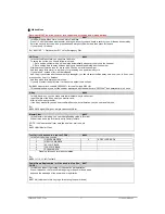
Emergency Battery Backup
Checking the Battery
Each Subscriber SXT-4080 unit comes with a standard internal battery inside, and can be replaced at
your local After-Service Centers.
Plug in Your Telephone
1) Locate the modular line port on your telephone and plug in one end of a standard phone cord
2) Connect the other end of the phone cord to the telephone port on the side of the Unit.
NOTE:
The SXT-4080 does not support direct computer modem (data) operation through the phone port or fax
port.
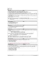
SXT-4080 OPERATION
Use the LED Status Indicators
1) Power-on the unit
2) The LEDs indicator on the front of the will turn ON. The following table describes the modes and
operations of the indicator.
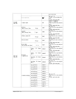
Status LED
#.
√
: Don’t care
Section
LED
Description
RSSI
BATT
Color
Blink
Color
Blink
1
Power ON
Green X None X
2
Boot sequence
Yellow X Yellow O
Booting…
3
Initialize done
Red O Red X
Idle status
4
Activation fail
Yellow/Red
O
√
√
MIN/ESN fail, etc..
5
Exception occur
Yellow X Red X
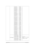
6
RSSI
High
Green X
√
√
RSSI < 98dB
7
Normal
Yellow X
√
√
98< RSSI < 104dB
8
Low
Red X
√
√
RSSI > 104dB
9
No signal
Red O
√
√
Searching…
10
Battery
High
√
√
Green X
Over 3.8V
11
Normal
√
√
Yellow X
Over 3.7V
12
Low
√
√
Red X
Over 3.4V
13
Low battery warn
√
√
Red O
Under 3.4V
14
Switch off
√
√
Yellow/Red
O
15
No battery
√
√
None X
Battery Strength Indicator
Low battery Tone
– Generated alert sound or blink power LED when battery low. In conversation generated
alert sound, not in conversation blink power LED.


