background image


60 


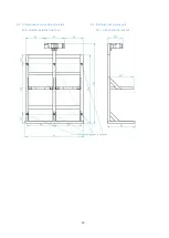
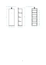
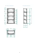
6.9.  Dimensiones del módulo de baterías 

6.9.5. Bastidor baterías Small 2x2 


6.9.  Batteries rack dimensions 

6.9.1. Small batteries rack 2x2 


Summary of Contents for P2S Series

Page 1: ...1 Manual de instalaci n Installation guide P2S Series plug single phase P2S powered by...

Page 2: ...2 Versi n 4 6 June 2018 Epic Power Converters S L...

Page 3: ...o 47 3 6 Otras conexiones 47 4 OPERACIONES DE MANTENIMIENTO 49 4 1 Mantenimiento del ascensor 49 4 2 Mantenimiento del P2S 50 5 PRECAUCIONES 51 Content of the guide 1 P2S GENERAL DESCRIPTION 5 2 P2S E...

Page 4: ...dium 62 6 10 Dimensiones del soporte cargador y ondulador 63 6 11 Dimensiones del armario completo precableado 64 7 REGLAMENTACI N Y NORMATIVA 65 6 DATOS T CNICOS DIMENSIONES Y PESOS TECHNICAL DATA DI...

Page 5: ...n muchos casos es lo que mayor coste acarrea en la factura de la luz Para conseguir un ascensor 100 sostenible durante las horas de luz el P2S tambi n permite el conexionado de placas solares 1 P2S GE...

Page 6: ...la potencia necesaria X Tabla 1 Potencia nominal convertidores DC DC P2S system consists of DC DC Converter EPCLL XXX XXX Battery charger HEP 600C Single Phase inverter 400W or 700W Batteries several...

Page 7: ...000W nominales para modelos EPCL 11k XXX Otros de elementos 230Vac m x 400W o 700W opcional o Alimentaci n maniobra frenos iluminaci n etc Supply Input 230Vac max 500W VVVF Supply Output 600Vdc nomina...

Page 8: ...muestran los distintos conectores del modelo EPCL 3k5 Fig 2 y del EPCL 5k5 Fig 3 2 1 DC DC Converter The next two figures show external connections of EPCL 3k5 model Fig 2 and EPCL 5k5 model Fig 3 Fi...

Page 9: ...9 Fig 3 Convertidor DC DC 5k5 5k5 DC DC Converter 0 1 2 3 4 6 10 9 7 8 5...

Page 10: ...N DE DERIVA Normally Open 1H No conectado El estado de los contactos en funci n del estado de carga de las bater as SoC es el siguiente cerrado 0 abierto 1 1 OUTPUTS TO CONTROLLER IMPORTANT These are...

Page 11: ...rada ENABLE INV 3C En caso de apagar el DC DC con el interruptor ON OFF el Inversor monof sico ser deshabilitado 2C y 2D Remote Control RC CHARGER y Deshabilita el cargador de bater as mediante cortoc...

Page 12: ...DC DC DC Converter enabling or disabling input To provide energy to the DC bus it is mandatory for the controller to short circuit terminals 3A and 3B o The controller may use this option to turn off...

Page 13: ...er This is only necessary if the solar charge controller has been acquired 5 Inverter POWER Salida de alimentaci n del variador N P 5 Inverter POWER Frequency controller output N P 6 CAN bus opcional...

Page 14: ...encendido del Convertidor DC DC En posici n OFF tanto la alimentaci n del variador como la salida 230Vac del inversor monof sico quedar n deshabilitadas independientemente de las se ales de ENABLE co...

Page 15: ...13 Conexi n AC Neutro AC N 14 Conexi n con el terminal RC CHARGER del convertidor DC DC RC 15 Conexi n con el terminal RC CHARGER del convertidor DC DC RC GND 16 No conectar 5VSB 17 Salida a borne Neg...

Page 16: ...del ascensor 23 Diodo LED Status verde 24 Pulsador de Setting permite cambiar la tensi n de salida entre 220Vac y 240Vac y la frecuencia entre 50Hz y 60Hz por defecto la salida se establece en 230Vac...

Page 17: ...rter Conectado al terminal 2A y 2B del convertidor 29 Entrada DC Positivo Bater a 30 Entrada DC Negativo Bater a 26 Fan 27 Ground connection 28 RC Connected to terminals RC inverter and RC inverter of...

Page 18: ...ifferent types of batteries are needed and should be installed according to elevator features elevator travel and rated load Thus three battery sizes are available SMALL MEDIUM and LARGE epic power wi...

Page 19: ...er a 3 37 Borne positivo de la bater a 4 38 Borne negativo de la bater a 4 39 Fusible con portafusibles 40 Fusible con portafusibles 31 Positive terminal of battery 1 32 Negative terminal battery 1 33...

Page 20: ...ble OEG EPCL CABLE OEA Conexi n de cargador de bater as e inversor monof sico Latiguillo de cuatro conductos de 2 5mm2 de secci n y 1m de longitud con terminal a reo en un extremo y terminales en U en...

Page 21: ...CL 3k5 trough a clablegland 25mm2 section but in the EPCL 5k5 the connection is through aerial connector 50 mm2 section Fig 11 EPCL Cable OEH EPCL CABLE OEJ_S OEJ_M 3 unidades Conecta bater as entre s...

Page 22: ...doble CABLE OEI conecta el terminal positivo de la bater a 1 con el alma roja del CABLE OEH es decir interta un fusible entre rl convertidor DC DC y las bater as CABLE OEM conecta el terminal negativo...

Page 23: ...CHARGER y RC CHARGER del convertidor DC DC con el conector del inversor monof sico y los terminales y del cargador de bater as EPCL CABLE OEB Four wire cable terminating in an aerial connector on one...

Page 24: ...open circuit voltage PV 150V Eficiencia m xima Maximum efficiency 98 Temperatura trabajo Working temperature 30 60 C Hasta 40 C para potencia nominal Peso Weight 1 25 Kg IMPORTANTE La tensi n FV debe...

Page 25: ...have to be connected in series to match the regulator requirements Fig 17 Regulador de carga solar Solar charger controller 2 41 BATTERY Conectado al punto del Convertidor DC DC mediante el cable roj...

Page 26: ...y A metallic plate can be purchased optionally for greater ease when installing and wiring the multiple components In this case the battery charger and the inverter are already installed and pre wired...

Page 27: ...las bater as Esta soluci n dispone de su propio manual de instalaci n 2 6 3 Prewired electrical cabinet A metallic cabinet can be purchased optionally for greater ease when installing and wiring the...

Page 28: ...s de 60 cm de longitud y preparado para colocar en carril DIN nicamente precisa conexi n al terminal positivo cable rojo y negativo cable negro del bus de continua del variador Delivered with 60cm lon...

Page 29: ...nillar con un tornillo de m trica M3 en el agujero especificado en la imagen inferior derecha 2 6 6 CAN interface module If CAN communication is required a CAN interface module is available Before the...

Page 30: ...ow 8C CAN High 8D Salida 5V 0 1A CAN 1 y CAN 2 est n electricamente aislados entre s CONNECTOR 8 CAN 2 8A GND 8B CAN Low 8C CAN High 8D 5V 0 1A Out CAN 1 and CAN 2 are electrically isolated Fig 23 Cab...

Page 31: ...informativos respecto al acceso al bus DC de distintos variadores o Es fundamental identificar perfectamente y con total seguridad estos terminales de lo contrario el sistema P2S o el variador podr an...

Page 32: ...y 13 mm Destornillador PH2 Destornillador torch Tx25 solo para EPCL 5k5 Destornillador plano 2 5 mm Taladro broca hormig n tacos tornillos para sujecci n en pared 230V AC Supply o P2S 230V AC inverte...

Page 33: ...icientemente largo v Las bater as y su bastidor deber n estar colocados y fijados en la posici n que aparece en esta imagen No coloque las bater as a m s de 3 metros del Convertidor DC DC ya que este...

Page 34: ...hem If one of this cables needs to be replaced you must use one with the same characteristics there should be no loose wires in the terminals In addition take into account that the effort to hold the...

Page 35: ...o Fig 8 medium Connect CABLE OEH black core to DC DC converter connector and to fuse holder terminal It is VERY IMPORTANT to observe polarity at DC DC converter connector During these steps keep the f...

Page 36: ...oras Bater as Medium tm x 8 horas Bater as Large tm x 13 horas ii Connecting the AC inverter Using CABLE OEA connect BATTERY TO INVERTER and BATTERY TO INVERTER from the DC DC converter to BROWN and B...

Page 37: ...50 V contin e al siguiente punto sino espere 5 En la parte inferior del Convertidor DC DC se encuentra el conector hembra para la conexi n al variador de frecuencia Inverter POWER Con el CABLE OEG se...

Page 38: ...never draw power above this level More information in section 3 5 Ajuste de la potencia m xima consumida por el motor Fig 28 Conexi n entre Convertidor DC DC y variador de velocidad DC DC converter to...

Page 39: ...ase but now there are two metal plates in the top corners As in the previous case put the M4 screws into the holes pictured Fig 30 Montaje chapa de cierre bastidor Small Assembly of the Small rack clo...

Page 40: ...de proporcionar un nivel de seguridad superior para el operario en caso de no conectarlo el P2S podr a llegar a da arse WARNING IT IS ESSENTIAL to earth the conductor minimum 2 5 mm2 section If the co...

Page 41: ...exi n del sistema P2S el m dulo de bater as permanecer cargado NO CORTOCIRCUITE BAJO NING N CONCEPTO LOS TERMINALES DEL M DULO DE BATER AS WARNING During CONNECTION of the battery array first connect...

Page 42: ...n AC Fase AC L iii 13 Conexi n AC Neutro AC N 2 Cierre el porta fusible ver Fig 14 3 4 P2S System Start Up 3 4 1 Before connecting Once Installation chapter has been completed you can proceed with th...

Page 43: ...Reference source not found tienen que estar cortocircuitados de manera externa iii Los terminales ENABLE DC DC y COMUN del Convertidor DC DC tienen que estar cortocircuitados de manera externa i The i...

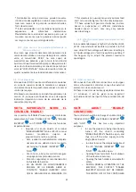
Page 44: ...quipos contacte con epic power 3 5 Maximum consumed power adjustment IMPORTANT As mentioned above DC DC converter is able to supply a limit power depending on the model see table 1 to the VVVF Drive T...

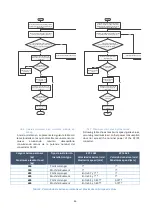
Page 45: ...e potencia ni tiene posibilidad de monitorizar el consumo en la pantalla Realizar los pasos indicados en el siguiente diagrama de flujo teniendo en cuenta los valores de potencia nominal mostrados en...

Page 46: ...nstalaci n y la carga m xima Realice un trayecto de bajada con la cabina vac a trayecto de m ximo consumo Se ha realizado el viaje exitosamente no se ha parado el variador y el consumo es menor que po...

Page 47: ...ado en la secci n 2 1 aunque a continuaci n se va a dar alguna indicaci n importante acerca de las entradas de la maniobra 3A 3B y 3C 3 6 Other connections P2S converter has different connections on i...

Page 48: ...nte para as deshabilitar la alimentaci n del variador De no hacerse as puede entra ar un grave peligro ya que el variador seguir alimentado permanentemente y el personal de mantenimiento puede sufrir...

Page 49: ...2S 7 Una vez hayan transcurrido unos 30 segundos encienda el P2S conmutando a ON y el interruptor del inversor monof sico 8 El ascensor volver a estar operativo alimentado desde el sistema P2S 4 MAINT...

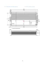
Page 50: ...a 4 6 Desconecte la bater a 1 con la bater a 2 7 Podr retirar las bater as y reemplazarlas por las nuevas 8 Para el proceso de instalaci n de las bater as siga el orden indicado en el punto 3 3 Insta...

Page 51: ...DEL P2S ya que se trata de un dispositivo de electr nica de potencia extremadamente complejo y requiere de personal altamente cualificado para su manipulaci n Cualquier manipulaci n inexperta podr a d...

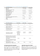
Page 52: ...ente almacenamiento Storage temperature 10 70 C 10 70 C 10 70 C 10 70 C Peso Weight 8 kg 11 kg 16 kg 22 kg Grado de protecci n IP IP protection class IP20 IP20 IP20 IP20 Condiciones clim ticas Climati...

Page 53: ...temperature 20 60 C 20 60 C 20 60 C Temperatura de trabajo Operating temperature 15 50 C carga charge 20 60 C descarga discharge 15 50 C 20 60 C 15 50 C 20 60 C Estimaci n de vida de las bater as supo...

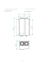
Page 54: ...54 6 5 Dimensiones del Convertidor DC DC Dimensiones EPCL 3k5 6 5 DC DC converter dimensions EPCL 3k5 dimensions...

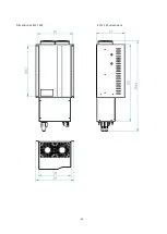
Page 55: ...55 Dimensiones EPCL 5K5 EPCL 5k5 dimensions...

Page 56: ...56 6 6 Dimensiones del cargador de bater as 6 6 Battery charger dimensions...

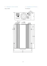
Page 57: ...57 6 7 Dimensiones del inversor monof sico 6 7 Single phase inverter dimensions Inversor TS 400 TS 400 Inverter...

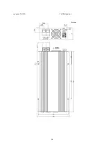
Page 58: ...58 Inversor TS 700 TS 700 Inverter...

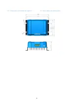
Page 59: ...59 6 8 Dimensiones del Controlador de carga solar 6 8 Solar charge controller dimensions...

Page 60: ...60 6 9 Dimensiones del m dulo de bater as 6 9 5 Bastidor bater as Small 2x2 6 9 Batteries rack dimensions 6 9 1 Small batteries rack 2x2...

Page 61: ...61 6 9 2 Bastidor bater as Small 4x1 6 9 2 Small batteries rack 4x1...

Page 62: ...62 6 9 3 Bastidor bater as Medium 6 9 3 Medium batteries rack...

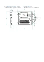
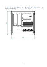
Page 63: ...3 6 10 Dimensiones del soporte cargador y ondulador El soporte opcional cargador ondulador tiene unas dimensiones de 430x380x90mm 6 10 Holder tray dimensions The holder tray dimensions are 430x380x90m...

Page 64: ...ones del armario completo precableado El armario completo precableado tiene unas dimensiones de 600x600x205mm 6 11 Electrical cabinet prewired dimensions The electrical cabinet prewired dimensions are...

Page 65: ...nto del mercado interior exigiendo que los equipos cumplan un nivel adecuado de compatibilidad electromagn tica UNE EN 12015 2005 UNE EN 12016 2014 7 REGULATIONS P2S system has been designed and manuf...

Reviews: