background image

22

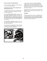
 HOW TO TURN ON THE POWER

IMPORTANT: If the elliptical has been exposed to 
cold temperatures, allow it to warm to room tem-
perature before you turn on the power. If you do 
not do this, you may damage the console displays 
or other electrical components.

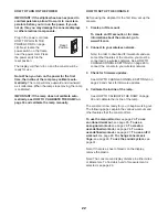
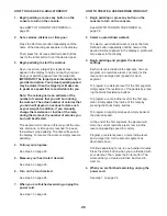
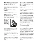
Plug in the power cord (see 
HOW TO PLUG IN THE 
POWER CORD on page 
18). Next, locate the 
power switch on the frame 
near the power cord. Press 
the power switch to the 
reset position.

The display will then turn on and the console will be 
ready for use.

Note: When you turn on the power for the 

 rst 

time, the incline of the ramp may calibrate auto-
matically.

 The ramp will move upward and downward 

as it calibrates. When the ramp stops moving, the ramp 
is calibrated. 

IMPORTANT: If the ramp does not calibrate auto-
matically, see HOW TO CALIBRATE THE RAMP on 
page 33 and calibrate the ramp manually.

HOW TO SET UP THE CONSOLE

Before using the elliptical for the first time, set up the 
console. 

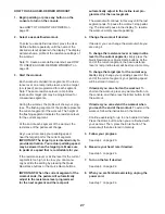
1.  Create an iFit account.


 To create an iFit account, or for more 
information about the account, go to 
www.iFit.com.

2.  Connect to your wireless network.


 Note: In order to download iFit workouts and use 
some other features of the console, you must be 
connected to a wireless network. See HOW TO 
CHANGE CONSOLE SETTINGS on page 29 to 
connect the console to your wireless network.

3.  Check for firmware updates. 


 See HOW TO CHANGE CONSOLE SETTINGS on 
page 29 and check for firmware updates.

4.  Calibrate the incline of the ramp.


 See HOW TO CALIBRATE THE RAMP on page 
33 and calibrate the incline of the ramp.


The console is now ready for you to begin working out. 
The following pages explain the various workouts and 
other features that the console offers.

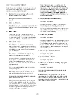
To use the manual mode,

 see page 23. 

To use 

an onboard workout,

 see page 25. 

To use a 

set-a-goal workout,

 see page 26. 

To create a 

user-defined workout,

 see page 26. 

To use a 

user-defined workout,

 see page 27. 

To use an iFit 

workout,

 see page 28. 

To change console set-

tings, 

see page 29.

 To use the sound system,

 see 

page 31. 

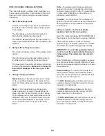
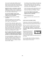
Note: If there is a sheet of plastic on the display, 
remove the plastic. 

Note: The console can display distance in either miles 
or kilometers. To find which unit of measurement is 
selected, see page 29. 

Reset 

Position

Summary of Contents for A30e Elliptical

Page 1: ...efore using this equipment Keep this manual for future reference www epicfit com ACTIVATE YOUR WARRANTY CUSTOMER CARE To register your product and activate your warranty today go to www epicfit com re...

Page 2: ...l in the location shown Note The decal s may not be shown at actual size WARNING DECAL PLACEMENT 2 IMPORTANT PRECAUTIONS 3 BEFORE YOU BEGIN 5 PART IDENTIFICATION CHART 6 ASSEMBLY 7 HOW TO USE THE ELLI...

Page 3: ...han 350 lbs 159 kg 11 Wear appropriate clothes while exercising do not wear loose clothes that could become caught on the elliptical Always wear athletic shoes for foot protection while exercising 12...

Page 4: ...4...

Page 5: ...ront cover of this manual To help us assist you note the product model number and serial number before contacting us The model number and the location of the serial number decal are shown on the front...

Page 6: ...m Screw 84 2 PART IDENTIFICATION CHART Use the drawings below to identify the small parts needed for assembly The number in parentheses below each drawing is the key number of the part from the PART L...

Page 7: ...o not dispose of the packing materials until you nish all assembly steps Left and right parts are marked L or Left and R or Right To identify small parts see page 6 In addition to the included tool s...

Page 8: ...izer 5 1 5 155 Wire Tie Wire Tie 155 Wire Tie 4 4 Tip Avoid pinching the Sensor Wire Harness 155 Set a sturdy piece of packing material under the rear of the Frame 1 Have a second person hold the Fram...

Page 9: ...e Rear Stabilizer Tip Avoid pinching the Sensor Wire Harness 155 Press the four Mounts 117 on the under side of the Rear Stabilizer Cover 2 into the Rear Stabilizer 5 5 2 5 155 147 117 Avoid pinching...

Page 10: ...through the Upright 4 Tip To prevent the Main Wire Harness 110 from falling into the Upright 4 secure the Main Wire Harness with the wire tie 110 4 1 110 Wire Tie Wire Tie Wire Tie 8 Tip Avoid pinchi...

Page 11: ...al 49 and the Right Pedal Arm 58 and orient them as shown Attach the Right Pedal 49 to the Right Pedal Plate 139 on the Right Pedal Arm 58 with four M6 x 14mm Screws 121 and four M6 Washers 90 Attach...

Page 12: ...95 Insert the Arm Axle 35 into the Upright 4 and center it Then slide a Wave Washer 95 onto each end of the Arm Axle With the help of a second person slide the Right Upper Body Leg 36 onto the right s...

Page 13: ...move the packaging from the wires on the Right and Left Handlebars 83 87 13 13 Slide the Right Upper Body Arm 61 onto the Right Upper Body Leg 36 Attach the Right Upper Body Arm 61 with two M8 x 35mm...

Page 14: ...60 62 56 87 104 83 14 Have a second person hold the Console 7 near the Console Bracket 62 Connect the Ground Wire 119 to the matching wire on the Console 7 Then insert all of the wires on the Console...

Page 15: ...upward and attach it to the Upright 4 with two M4 x 16mm Screws 104 17 17 Attach the Accessory Tray Base 8 to the Upright 4 with two M4 x 16mm Screws 104 104 104 80 8 4 4 18 18 Press the Accessory Tr...

Page 16: ...67 to the Right Upper Body Leg 36 with an M4 x 16mm Screw 104 Then press the Right Arm Lower Cover 68 onto the Right Arm Upper Cover 67 Attach the Left Arm Upper Cover not shown and the Left Arm Lowe...

Page 17: ...he elliptical to protect the floor 22 While a second person tips the elliptical to the left and holds it attach a Stabilizer Cap 134 to the right side of the Frame 1 with two M4 x 16mm Screws 104 Next...

Page 18: ...The lug or wire extending from the adapter must be connected with a metal screw to a permanent ground such as a properly grounded outlet box cover Some 2 pole receptacle outlet box covers are not gro...

Page 19: ...ove the elliptical to the desired location and then lower it to the oor HOW TO ADJUST THE POSITIONS OF THE PEDALS Each pedal can be adjusted to several positions To adjust each pedal lift the pedal an...

Page 20: ...on Then step onto the other pedal Push the pedals until they begin to move with a continuous motion Note The crank arms can turn in either direction It is recommended that you turn the crank arms in t...

Page 21: ...s and the incline of the ramp and prompts you to vary your pedaling speed as it guides you through an effective workout You can also set a time distance or calorie goal The console also offers user de...

Page 22: ...rmation about the account go to www iFit com 2 Connect to your wireless network Note In order to download iFit workouts and use some other features of the console you must be connected to a wireless n...

Page 23: ...pprox imate number of calories you have burned Calories per Hour Calories Hr This display mode will show the approximate number of calories you are burning per hour Distance This display mode will sho...

Page 24: ...automatically 5 Measure your heart rate if desired If there are sheets of plastic on the metal contacts on the handgrip heart rate monitor remove the plastic To measure your heart rate hold the handgr...

Page 25: ...target rpm for the current segment IMPORTANT The target rpm is intended only to provide motivation Your actual pedaling speed may be slower than the target rpm Make sure to pedal at a speed that is c...

Page 26: ...sired See step 5 on page 24 6 Turn on the fan if desired See step 6 on page 24 7 When you are finished exercising unplug the power cord See step 7 on page 24 HOW TO CREATE A USER DEFINED WORKOUT 1 Beg...

Page 27: ...he Quick Resistance buttons or the Quick Ramp buttons IMPORTANT When the current segment of the workout ends the pedals will automatically adjust to the resistance level programmed for the next segmen...

Page 28: ...ow the name duration maximum ramp incline level and distance of the workout The display will also show the approximate number of calories you will burn during the workout and a profile of the resistan...

Page 29: ...ress the Enter button Units The selected unit of measurement will appear in the matrix To change the unit of mea surement press the Enter button To view distance in miles select ENGLISH To view distan...

Page 30: ...to select the letter number or symbol When you have finished entering the password press the Done button Next a numerical code and a web address will appear in the matrix Open a web browser on your co...

Page 31: ...T_SETUP The console will display an IP address such as 192 168 0 1 8080 Open a web browser on your computer smart phone tablet or other Wi Fi device Next type in the IP address on the con sole into th...

Page 32: ...t off and on try to correct the interference by one or more of the following measures Reorient or relocate the receiving antenna Increase the separation between the equipment and the receiver Connect...

Page 33: ...calibrate the ramp The ramp will move upward and downward as it calibrates When the ramp stops moving the ramp is calibrated Then press the User Defined button repeatedly until the last screen of the...

Page 34: ...Crank Arm Cover 71 off the Left Front Shield 73 Next locate the Reed Switch 38 Turn the left Crank Arm 20 until one of the Magnets 43 on the Pulley 19 is aligned with the Reed Switch Loosen but do no...

Page 35: ...c Exercise If your goal is to strengthen your cardiovascular system you must perform aerobic exercise which is activity that requires large amounts of oxygen for prolonged periods of time For aerobic...

Page 36: ...lles Stretch With one leg in front of the other reach forward and place your hands against a wall Keep your back leg straight and your back foot flat on the floor Bend your front leg lean forward and...

Page 37: ...37 NOTES...

Page 38: ...38 NOTES...

Page 39: ...53 6 Axle Cover 54 1 Left Arm Upper Cover 55 1 Left Arm Lower Cover 56 1 Upper Handlebar Cover 57 8 Roller Arm Pedal Arm Bushing 58 1 Right Pedal Arm 59 4 Flex Bracket Bushing 60 1 Lower Handlebar Co...

Page 40: ...r Cap 135 1 Left Pedal Adjustment Bracket 136 2 Pedal Arm Flex Bracket 137 8 Flex Bracket Cover 138 1 Left Pedal Plate 139 1 Right Pedal Plate 140 2 Pedal Plate Spring 141 2 Pedal Knob Cap 142 2 Pedal...

Page 41: ...132 98 72 72 117 16 17 40 85 86 78 99 105 13 125 32 32 97 125 108 108 131 131 107 127 127 127 124 127 147 15 104 118 38 104 39 18 120 120 111 102 102 19 43 43 23 104 104 2 65 89 109 101 88 40 105 150...

Page 42: ...5 130 140 148 53 46 99 82 136 136 133 149 133 149 133 133 59 90 90 59 104 104 104 98 53 53 137 104 143 121 137 137 137 137 104 104 148 104 53 72 72 33 72 72 59 59 58 98 53 41 61 68 67 48 95 70 98 36 7...

Page 43: ...119 100 100 153 154 100 122 122 128 128 100 126 73 76 77 71 71 104 117 72 72 72 72 62 104 104 104 104 104 104 104 104 50 81 79 64 121 123 52 87 35 98 98 56 30 30 66 8 60 72 72 75 83 91 80 37 4 7 69 6...

Page 44: ...imal handling charge For in home service the customer will be responsible for a minimal trip charge This warranty does not extend to freight damage to the product This warranty will automatically be v...

Reviews: