Epcom 1KVAH-RT User Manual Download Page 7

Epcom Power Line

 6

  | RT Series True Online UPS


 RT Series True Online UPS  |

 7


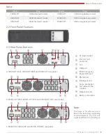
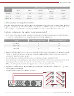
Normally, output connection of 1~3KVA series is configured with power outlets or terminal blocks, users can 

plug the load cable into the UPS power outlets to energize the load. Make sure the mains cable and breakers 

in the building are enough for the rated capacity of UPS to avoid the hazards of electric shock or fire.

3.3  Installation and Output Connection

3.4  External Batteries Connection (Long backup model)

Model

Wiring spec (AWG)

Input

Outpu

Battery

Non-isolated

Neutral

Ground

1KVAH-RT

1 mm²

1 mm²

4 mm²

1 mm²

1 mm²

2KVAH-RT

1.5 mm²

1.5 mm²

4 mm²

1.5 mm²

1.5 mm²

3KVAH-RT

2.5 mm²

2.5 mm²

4mm²

2.5 mm²

2.5 mm²

Model

Battery Quantity (unit)

Battery Voltage (volt)

1KVAH-RT

3

36

2KVAH-RT

6

72

3KVAH-RT

8

96

•  For different UPS model, users are instructed to configure different battery voltage as below table. More 

or less units are forbidden, or else something abnormal or faulty will appear.

•  One end of battery cable is for UPS terminals while the other end with triple cables is for battery terminals. 

Correct installation procedure is highly vital or else probable electric shock will arise. Users are strictly 
required to follow the below procedure.

•  Connect batteries correctly and make sure the total battery voltage is available for UPS.
•  Correctly connect the long battery cable to battery terminals first, red wire is to positive plate while black 

is to negative. If users connect the UPS first, electric shock or other danger may not be avoided.

•  Before connecting loads, users should supply mains power and energize the UPS.
•  Connect long battery cable to UPS terminals with correct poles link (red is for ‘+’, black is for ‘-‘), UPS will 

start charging automatically.

•  Connect the battery pack to the battery connector.

Summary of Contents for 1KVAH-RT

Page 1: ...Epcom Power Line RT Series True Online UPS 1 RT Series User Manual TRUE ONLINE UPS 1KVA 3KVA...

Page 2: ...may cause electric shocks and have a high short circuit current follow below requirements before installing or replacing the batteries 1 1 UPS Safety Information Note Symbol Instructions 1 2 Battery...

Page 3: ...and 100 load 176 280Vac no derating 280 300Vac power derating 50 Input frequency range 40 70Hz PFC 0 99 THDI 6 Bypass voltage range 25 15 settable Output Output voltage 208Vac 220Vac 230Vac 240Vac set...

Page 4: ...over 90 capacity in 3 hours for standard models Charging current Max Standard model 1 A 0 15 Long time model 6 A 3 A 0 5 System Control and Communications Protections Over temp protection Fan testing...

Page 5: ...it might be different from the figure Model Type Model Type 1KVAS RT 1KVA Standard model 1KVAH RT 1KVA Long backup model 2KVAS RT 2KVA Standard model 1KVAH RT 2KVA Long backup model 3KVAS RT 3KVA Stan...

Page 6: ...it to UPS and then turn on the load one by one later Connect the UPS with the power outlet which is over current protected Do not connect the UPS with power outlets whose rated current is less than th...

Page 7: ...are instructed to configure different battery voltage as below table More or less units are forbidden or else something abnormal or faulty will appear One end of battery cable is for UPS terminals whi...

Page 8: ...s green Users can cut off the output of UPS immediately by operating EPO port in case of emergency Normally pin1 and pin2 are connected so that the machine can be working normally When some emergenci...

Page 9: ...the rear panel of the UPS it s for SNMP card and dry contacts Users can insert any type intelligent card from those three into it to monitor and manager the UPS And users don t have to turn off the UP...

Page 10: ...ode Press or for more than half a second less than 2 seconds display the items orderly Press for more than 2 seconds Circularly and orderly display the items every 2 seconds when press the key for som...

Page 11: ...ntage 0 25 26 50 51 75 and 76 100 is indicated by the number of load bar sections illuminated When UPS is overloaded the load icon will flash Mute Icon Indicates the audible alarm is disabled mute Pre...

Page 12: ...ormation Digital Display Area In non setting mode it displays UPS output information when UPS normally runs Fault code will be told in fault mode In setting mode users could adjust different output vo...

Page 13: ...rt UPS The operation of UPS startup process is almost same as above process with mains power After the self test finishes UPS will work in battery mode Turn Off the UPS Turn off the UPS in Line mode P...

Page 14: ...erical value press and hold the function setting for more than half a second less than 2 seconds Now the setting function is completed and the numerical value illuminates without flashing Exit from th...

Page 15: ...D voltage automatically varies with loads including 21 5 hours dicharge protection Frequency Converter Enable Disable C L I N E 22 0 s0 0 25 50 75 100 25 50 75 100 VAC Hz L I N E 25 50 75 100 25 50 75...

Page 16: ...display will have nine option 240V 230V 220V 208V 100V 110V 115V 120V 127V but the voltage output is still four option 240V 230V 220V 208V You can choose to shield the LCD display capacity values when...

Page 17: ...0 75 100 25 50 75 100 w KVA L I N E 900 10 25 50 75 100 25 50 75 100 L I N E C 40 25 50 75 100 25 50 75 100 VAC Hz L I N E 220 500 75 100 75 100 S T D B Y 220 25 50 75 100 25 50 75 100 V S T D B Y 600...

Page 18: ...up is ON Turn off the UPS in line mode and the bypass setup is ON Overload in line mode Note When UPS is working in bypass mode it has no back up function Line Mode Being in line mode are as following...

Page 19: ...he UPS turns to fault mode UPS cuts off the output and LCD displays fault codes At the moment users can press the mute key to make the buzzer stop beeping temporarily to wait for maintenance Users can...

Page 20: ...nder Bypass Working mode displays byPASS One beep 2 mins Mains power high voltage war ning under Bypass Working mode displays byPASS One beep 4 sec Mains power low voltage warning under Bypass Working...

Page 21: ...m code S N Working Status LCD Display Messages Alarm Beep 5 Output Overload Protection Warning for mains power overload Working mode displays Line load icon flash 2 beeps sec Protect operation for mai...

Page 22: ...left Display Value Bypass Lost Remote Shutdown Overload Battery Disconnected 0 1 2 3 4 5 6 7 8 9 A B C D E F The second digital tube from right to left Display Value Overcharging Warnings Mains Revers...

Page 23: ...Value EEPROM Abnormal Fan Abnorma Low Battery Low Battery 0 1 2 3 4 5 6 7 8 9 A B C D E F The fourth digital tube from right to left Display Value Over Load Fault Mains Lost Bypass Abnormal 0 1 2 3 4...

Page 24: ...plier Fault icon display audible buzzer alarm continually the fault code is 40 44 Over temperature inside overloaded and the fan vent is not obstructed as well as the indoor temperature is not high Le...

Page 25: ...fail to start when operate On key Pressing time too short Press the power key more than 2 seconds to start the UPS The input connection is not ready or UPS internal battery disconnect Connect the inp...

Page 26: ......

Reviews: