Druck-Nr.:
2902 5160
Stand:
17.2021
EN
Made in Germany
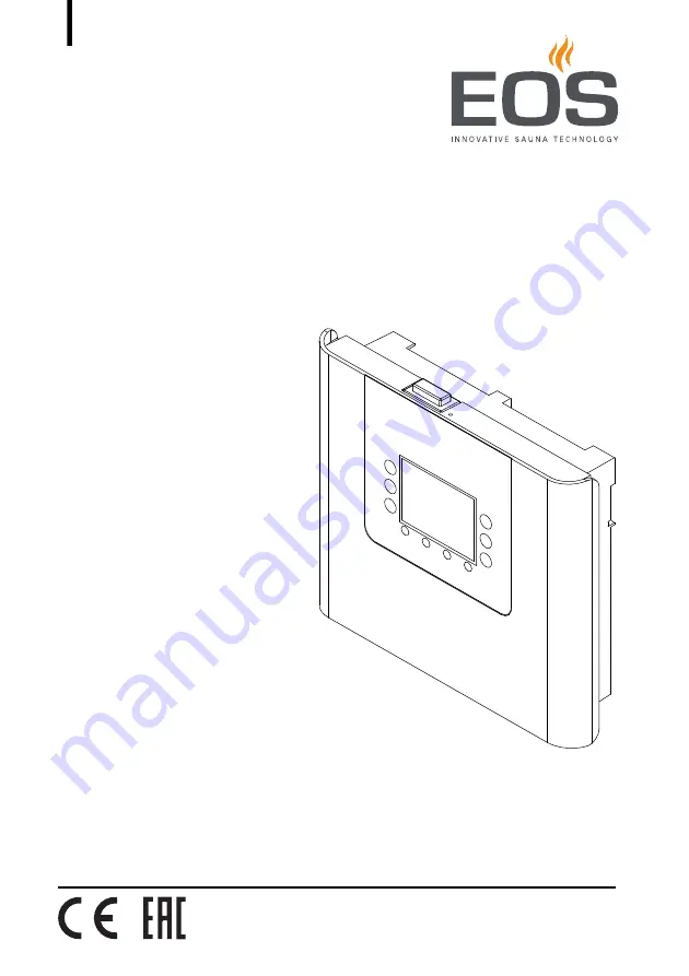
EOS Compact DP/HP
Control Unit for Sauna Cabins
Installation and Operating Instructions
Page 1: ...Druck Nr 2902 5160 Stand 17 2021 EN Made in Germany EOS Compact DP HP Control Unit for Sauna Cabins Installation and Operating Instructions ...
Page 2: ...permit ted Compensation will be claimed in the event of infringements All rights reserved with regard to patent claims or submission of design or utility patent Characters symbols and illustrations Revision history EOS Saunatechnik GmbH Schneiderstriesch 1 35759 Driedorf Germany Tel 49 2775 82 514 Fax 49 2775 82 431 Email servicecenter eos sauna com Web www eos sauna de Additional information abou...
Page 3: ...essories EN 15 2 6 Intended use EN 15 3 Installation EN 16 3 1 Routing the lines EN 16 3 2 Installation site EN 17 3 3 Mounting the control unit EN 20 3 4 Mounting the heater sensor EN 28 3 5 Mounting the cabin lighting EN 33 3 6 Mounting the fan EN 33 4 Connecting the lines EN 34 4 1 Circuit board assignment for EOS Compact HP EN 36 4 2 Circuit board assignment for EOS Compact DP EN 37 4 3 Connec...
Page 4: ...g the light on off EN 57 6 7 3 Selecting Finnish Bi O mode EN 58 6 7 4 Temperature EN 58 6 7 5 Setting the humidity for Bi O mode EN 58 6 7 6 Heating period auto stop EN 59 6 7 7 Timer EN 60 6 7 8 Profiles EN 61 6 7 9 HOT mode intense heating EN 61 6 7 10 ECO mode temperature decrease EN 62 6 7 11 Retrieving temperature humidity values EN 62 6 7 12 Switching the fan on off manually EN 63 6 8 Advan...
Page 5: ...EOS Compact DP HP Installation and Operating Instructions EN 5 8 Troubleshooting EN 69 8 1 Error messages EN 69 8 2 Malfunction EN 71 9 General terms and conditions of service EN 72 10 Disposal EN 75 ...
Page 6: ...are clas sified Please familiarise yourself with the following terms and symbols WARNING Warning Indicates a hazardous situation which if not avoided could result in death or serious injury CAUTION Caution Indicates a hazardous situation which if not avoided could result in minor or moderate injury NOTICE Notice Indicates a hazardous situation which if not avoided will result in damage to the unit...
Page 7: ...it and other electrical systems or equipment with a fixed mains connection may be performed only by a trained electrician from an authorised elec trical company Ensure compliance with the applicable standards and regula tions for electrical installation The system must be disconnected and removed entirely from the mains supply before commencing installation and repair work The housing cover must o...
Page 8: ...such as extreme humidity and moisture or the possible formation of condensation or cor rosive substances in the ambient air as well as other weather conditions Similarly excessivecoldandextremeexposuretosunlightmust be prevented Protect the unit accordingly if there is an increased risk of me chanical damage 1 3 Operator instruction The operator of the sauna cabin must be instructed in the general...
Page 9: ...spare parts from the manufacturer Health risks Spending time in an infrared or sauna cabin can lead to serious health risks or even death for persons with health impairments Persons with health impairments who spend time in a sauna must consult a doctor before entering an infrared or sauna cab in Equipment damage due to overuse Excessive humidity in commercial infrared or sauna cabins can lead to ...
Page 10: ...sed by an adult The sauna cabin must only be used by persons with reduced mental capacity or limited physical or sensory abilities under supervision or if theyhave alreadybeen instructedin its useand understand the risks Children and persons who have not received proper instruction must not clean or service the system 1 4 Standards and regulations For an overview of the standards that were observe...
Page 11: ...pact HP Finnish or steamy hot air bath mode This documentation describes both models 2 1 Scope of delivery Scope of delivery Check the scope of delivery for completeness prior to installation A EOS Compact control unit B Installation and Operating Instructions C 2 screws to attach the heater sensor 3 x 25 mm D Heater sensor with safety temperature limiter E Sensor and safety temperature limiter ca...
Page 12: ...plate example A Name B Model C Item number D Operating voltage E Switching output F Country of origin G Manufacturer H Manufacturing date I Serial number Saunasteuergerät Control unit Type EOS Compact Art Nr 94 XXXX 00 400 V 3N AC 50 Hz Max Schaltleistung 10 kW Made in Germany EOS SAUNATECHNIK GmbH Schneiderstriesch 1 35759 Driedorf S No 0121 00001 IPX4 A B C D E F G H I ...
Page 13: ...e sauna cabin is set via the control unit The set values are checked by the heater sensor It controls the temperature in the sauna cabin The heater sensor has a safety temperature limiter which ensures that the temperature does not exceed 140 C Internal view of heater sensor A Temperature sensor B Safety temperature limiter A B ...
Page 14: ...ure control range Finnish sauna mode 30 115 C Steamy hot air bath Bi O 30 70 C Humidity control HP only Cycle 1 100 in proportion to time for active humidity mode Water level monitoring HP only Detects water shortage with automatic switch off after 3 minutes only with compatible sauna heater Connection for lighting Max 100 W 20 mA Fan and light connections are protected by a joint 2A F fuse Connec...
Page 15: ...or outdoor use It must be operated only inside buildings and may not be exposed to environmental conditions such as extreme humidity and moisture or the possible formation of condensation or corro sive substances in the ambient air as well as other weather conditions Similarly excessive cold and extreme exposure to sunlight must be prevented Protect the unit accordingly if there is an increased ri...
Page 16: ...lec tronics malfunctions because e g because the sensor will not be detected Do not route the sensor cables together with power supply lines Route cable ducts separately Data lines must be routed and connected in such a way that they are not openly accessible They should be routed between the insulation and the outer wall of the cabin Cabin insulation must be installed in such a way that the tempe...
Page 17: ...of the sauna cabin Observe the following guidelines WARNING Risk to life and limb and risk of fire Risk to life and limb from electric shock and fire in the event of im proper or faulty electrical connection This risk also applies follow ing completion of the installation work Do not mount the control unit in enclosed cabinets or wood panelling ...
Page 18: ...EN 18 Installation and Operating Instructions EOS Compact DP HP EN Installation Proper and improper mounting of the control unit ...
Page 19: ...Precipitation humidity extremely high low outdoor tempera tures and direct sunlight can damage the unit since it was not de signed for outdoor use Mount the control unit inside the building We recommend mounting the control unit on the cabin s exterior wall Mounting on the cabin s exterior wall A Eye level ca 350 mm A ...
Page 20: ...control unit and system downtime Mount the control unit outside of the area in which the humid warm air mixture can spread Mount the control unit on the hinge side of the door Tools required Saw for cutting the wall only when mounting in the wall Screwdriver 2 mm included in the scope of delivery Taut wire as needed Wooden screws included in the scope of delivery 3 pcs when mounting on the wall Th...
Page 21: ...ions EN 21 Installation Removing the front cover 1 Remove the front cover from the housing a Unscrew the screw on the top of the housing b Swivel the front cover and remove it downward Remove the protective film from the panel after mounting is completed ...
Page 22: ...rating Instructions EOS Compact DP HP EN Installation Preparing the air inlets 1 Specifying the line openings in the housing A Openings sensor line s B Openings mains supply line heater output vaporiser supply line light fan B A ...
Page 23: ... Instructions EN 23 Installation 2 Preparing the line openings a Break the plates from out of the openings b Insert the bushings Mounting the control unit on the wall 1 Drill one 1 hole above and two 2 holes below A Plates B Bushings A B 165 165 ...
Page 24: ... Instructions EOS Compact DP HP EN Installation 2 Tighten the upper screw Allow the screw to protrude approx 3 mm so you can hook in the housing 3 Pull the lines through the openings in the housing See Preparing the air inlets EN 22 3 ...
Page 25: ... Mount the housing on the wall a Hook the housing into the upper screw using the upper mounting hole A b Securely tighten the housing in the two lower clearance holes B Next step 4 Connecting the lines EN 34 A Upper mounting hole for screw B Lower mounting holes for screws A B B ...
Page 26: ...Installation and Operating Instructions EOS Compact DP HP EN Installation Mounting the control unit in the wall 1 Prepare a wall cut out Height x width 198 x 215 mm mounting depth min 35 mm 0 5 35 0 5 198 215 ...
Page 27: ...ill four holes a set the housing in the wall cut out b Use a pencil to mark the four drill holes in the tabs c Remove the housing d Drill four holes 3 Pull the lines through the openings in the housing See Preparing the air inlets EN 22 A Tabs with mounting holes for screws A A A A ...
Page 28: ...ater sensor must be installed where expected temperatures are the highest meaning directly above the sauna heater Proper installation is necessary to ensure compliance with the temperature limits and to ensure that there is only a very slight fluctuation in temperature in the areas of the sauna cabin where there are reclining options Hardware tools Heater sensor and connecting cables Drill used to...
Page 29: ...o installing the heater sensor may exist for certain sauna heaters Ensure that there are no heater specific requirements that ap ply to installing the sensor Observe the installation and operating instructions for the sau na heater A Cabin ceiling B Heater sensor housing C Line for temperature sensor 2 pole D Line for safety temperature limiter 2 pole A B C D ...
Page 30: ...ed on the cabin ceiling above the sauna heater It is installed in observance of the following distances from the cabin wall depending on the cabin size 2 Drill a hole in the cabin ceiling for the cable 3 Route the sensor cable through the hole Attach a taught wire to the cable as needed A Cabins smaller than 2x2 m Distance from wall 19 cm B Cabins larger than 2x2 m Distance from wall 35 cm 35 cm 1...
Page 31: ...n for lines to the receiving disk If multiple sauna heaters are installed in a sauna cabin it may be necessary to install additional safety temperature limiters and connect them in series 5 Insert the receiving disk in the bottom of the housing A Connection for safety temperature limiter B Connection for temperature sensor line C Temperature sensor D Safety temperature limiter A C B B A D ...
Page 32: ...EN Installation 6 NOTICE Do not damage the sensor cables when installing Attach the housing to the cabin ceiling a Screw in the bottom of the housing with the receiving disk to the cabin ceiling b Attach the top of the housing 4 3 Connecting the sensor cables EN 38 ...
Page 33: ...s for lighting Light source requirements Minimal output 5 W Maximum output 100 W 3 6 Mounting the fan An exhaust fan can be mounted in the cabin and set via the control unit The fan can be installed anywhere however never near hot air that rises from the heater The fan is not included in the scope of delivery Observe the separate installation instructions for the fan Fan requirements Minimal outpu...
Page 34: ...moisture has escaped from the heating elements after approx 10 minutes the RCD can be integrated again in the electric circuit If the sauna heater will not be used for an extended period of time we rec ommend that you switch on the heater every 6 weeks so that the heating elements do not accumulate moisture If during commissioning the RCD is triggered the electrical installation must be checked ag...
Page 35: ...nt settings must be made they will be referred to specifically by name Recommended installation sequence Before commencing installation the control unit must be mounted Fur thermore all cabin work must be complete sauna heater sensor light etc Complete installation in the following sequence Connect the sensor lines Connect the consumer lines for sauna heater light fan etc Check the setting for the...
Page 36: ...put controller B Heater sensor connection C Safety temperature limiter connec tion D Heater sensor with safety tempera ture limiter E Safety system jog dial F Heating period limitation jog dial G Cabin lighting H Fan I Vaporiser J Sauna heater N V1 S1 L1 L2 L3 N N W V U N WB L1 L2 L3 N 400V 3N AC 3x16A N V1 S1 WM FNFL LN LL STB STB P max 3 kW P max 10 kW Wb PE Wm N LSG D C A G H J B E F I ...
Page 37: ... EOS Compact DP A Output controller B Heater sensor connection C Safety temperature limiter connec tion D Heater sensor with safety tempera ture limiter E Safety system jog dial F Heating period limitation jog dial G Cabin lighting H Fan I Sauna heater N V1 S1 L1 L2 L3 N W V U N L1 L2 L3 N 400V 3N AC 3x16A FNFL LN LL STB STB P max 10 kW LSG N V1 S1 D C A G H B E F I ...
Page 38: ...l unit has no power Required tools Flathead screwdriver The front cover must be removed for the following steps See Removing the front cover EN 21 The cable is connected to a plug that can be removed from the circuit board This plug should be removed so that the cable can be connected easily and safely When the cable is connected the plug is plugged in again to the circuit board A Terminal plug fo...
Page 39: ...nsor a Connect the cable for the temperature sensor from the heater sensor to the two Oven Sens terminals b Connect the cable for the safety temperature limiter from the heater sensor to the two STB terminals on the lower main circuit board 2 Plug the terminal plug into the circuit board again as assigned S T B Oven Sens S T B Oven Sens ...
Page 40: ...ter 1 Connect the cable from the sauna heater to the four terminals heater W V U N and PE Always connect the neutral conductor N of the sauna heater as well because in humidity mode one phase is rerouted from the sauna heater to the vaporiser This results in an asymmetrical heating load and power flows through the neutral conductor The switching output of the control unit for the sauna heater has ...
Page 41: ...abin light 1 Connect the cable of the sauna lighting to the two terminals LN and LL Connecting the fan 1 Connect the fan to the two terminals FN and F1 N V1 S1 L1 L2 L3 N N W V U N WB LN FN WM FL LL M A I N S O V E N VA P L S G N V1 S1 L1 L2 L3 N N W V U N WB LN FN WM FL LL M A I N S O V E N VA P L S G ...
Page 42: ...ettings Private sauna operation without safety system The heating period is restricted to 6 hours irrespective of the set jog dial position for heating period limitation Private sauna operation with safety system The heating period is restricted to 6 hours irrespective of the set jog dial position for heating period limitation Commercial sauna operation without safety system Commercial sauna opera...
Page 43: ...tings Max 6 hrs runtime private or commercial operation Max 12 hrs runtime commercial operation e g in blocks of flats and hotels Max 18 hrs runtime commercial operation and if the cabin is con tinuously supervised e g in public saunas In Bi O mode a max of 17 30 hrs can be set since 0 30 hrs are included for the drying program Infinite runtime 24 hrs 7 days commercial operation and if the cabin i...
Page 44: ... the cable from the vaporiser to the three terminals VAP a Connect the brown cable to terminal WM b Connect the neutral conductor blue cable to terminal N c Connect the black cable to terminal WB The switching output of the control unit for the vaporiser has a max of 3 kW resistive load It can be expanded as needed by an optional output controller LSG You can connect more than one vaporiser If cor...
Page 45: ...he switching output of the control unit for the vaporiser has a max of 3 kW resistive load It can be expanded as needed by an optional output controller LSG You can connect more than one vaporiser Connecting the output controller LSG 1 Connect the LSG cable to the three terminals LSG V1 N and S1 An output controller is required for heaters with an output capacity of 10 5 kW or higher See the insta...
Page 46: ...tion As a rule only a fixed connection may be connected to the mains supply whereby a configuration is provided that makes it possible to separate the system from the mains supply with a contact opening width of at least 3 mm all poles 4 5 Checking for proper installation of the vaporiser If installed properly the vaporiser will switch on and off according to the humidity setting If the Wb and Wm ...
Page 47: ...tically in standby mode if it is connected to the mains supply and the rocker switch is set to position I The settings must be reset after a system reset The program guides you through the required steps Ensure that the rocker switch is set to Position I Menu navigation Setting set point values Reset value Next step Previous step I II 0 ...
Page 48: ... manually If the fan is switched on during the heating process it is switched off automatically when the heating process ends If the fan is switched on when the sauna cabin is in standby mode it is switched off automatically after 30 min You can set the fan function for Bi O mode humidity mode The func tion is set by the factory so that the fan can be switched on or off manu ally via the menu If a...
Page 49: ... can be switched on and off manually via the menu 1 Fan switched on in heater intermission 2 Fan switched on in heater heat up phase 3 Fan switched on in heater intermission and heater heat up phase 4 Fan switched on in vaporiser intermission 5 Fan switched on in vaporiser heat up phase 6 Fan switched off in heater intermission and heater heat up phase supplemental heating program Fan cannot be sw...
Page 50: ...er switch on control unit Switch on control unit Control unit is switched on factory setting Switch off control unit Control unit is switched off Parts of the circuit board are still energised Switch on light only Cabin light is switched on control unit and sauna heater are switched off Setting for cleaning and maintenance I II 0 I II 0 I II 0 ...
Page 51: ...ched off and no button is pushed Screen saver and sleep mode are ended by pressing any button A Status bar B Function menu item C Soft key activate function open menu item D Settings display E Switch sauna cabin on off F Down G Up H Switch cabin lighting on off After 1 hr Screen saver is activated After 2 hrs Sleep mode is activated screen is off 1 70 C 40 10 32 H G F E C B A D ...
Page 52: ...er opening a function or a menu item number val ues that can be changed appear in blue Save settings Set values are saved automatically Change to main menu If 5 seconds pass and no button is pressed the dis play returns automatically to the main menu Press the function soft key or the menu item again Navigate back with the arrow keys ...
Page 53: ...enu The displayed functions or menu items can vary depending on the control unit model and its configuration A Time status display B Bi O or Finnish operating mode C Target temperature humidity display D Target temperature E Target humidity F HOT mode G ECO mode H Fan I Autostop for heating period J Timer K Profiles L Operating data M Settings 1 70 C 40 10 32 70 C 40 10 32 B D E A F G H I J K L C ...
Page 54: ...in Bi O mode only Time or time remaining Time Time remaining in heating period until autostop Time remaining for HOT mode Time remaining for ECO mode Function mode active Cabin light is on Keypad lock is active Timer one time heating period is set Timer flashes recurring heating period is set Holiday cottage mode is active HOT mode is active Holiday resort mode is active ECO mode is active 70 C 70...
Page 55: ...or 2 seconds Status bar display during active keypad lock 6 5 Display settings 6 5 1 Time Setting the time 1 Open the Time menu 2 Set the time with Hours are changed by setting the minutes 6 5 2 Display brightness Setting the display brightness 1 Open the Display Brightness menu 2 Set the brightness with a b c 00 00 23 59 a b c 25 50 75 or 100 ...
Page 56: ...e logo is dis played The Setup menu opens For information on settings in the Setup Reset menu see 5 1 Setup EN 47 6 7 Sauna controls 6 7 1 Switching the sauna heater on off Switching on the sauna heater 1 Press the On Off button for 4 seconds A countdown is displayed The sauna heater is switched on The icons for temperature and humidity in Bi O mode only in the main menu are displayed in colour a ...
Page 57: ...is program continues to run the sauna heater for up to 30 minutes press again to cancel the drying program 6 7 2 Dimming or switching the light on off The light can be dimmed only if it has been configured as dimmable Switching the light on off 1 Briefly press the light button Status bar display if the light is switched on Switching on light only during cleaning maintenance 1 Set rocker switch to ...
Page 58: ...ure with During the heat up phase the temperature icon flashes in the main menu display 6 7 5 Setting the humidity for Bi O mode The humidity is set as a cycle This cycle defines the length of the active humidity mode in relation to the entire operating time For example the humidity setting 40 means the vaporiser is on approx 40 of the total operating time This setting does not take into considera...
Page 59: ...in operation mode The heating period in progress is not altered by this The new heating period starts only after heating is switched on again The heating period cannot be set in the holiday resort mode See 6 8 3 Modes holiday cottage holiday resort EN 65 Setting the heating period 1 Choose the Heating Period function 2 Set the heating period with In commercial operation the adjustable heating peri...
Page 60: ...This system must be con firmed during setup See 5 1 Setup EN 47 The timer cannot be set in the holiday resort mode See 6 8 3 Modes hol iday cottage holiday resort EN 65 Setting the timer 1 Choose the Timer function 2 Set the automatic start time with 3 Start the timer Commercial use in the sauna cabin Heating period limi tation Adjustable heating period 06 00 00 30 06 00 hr 12 00 00 30 12 00 hr 18...
Page 61: ...ved for this particular profile Profiles cannot be set in the holiday resort mode See 6 8 3 Modes holiday cottage holiday resort EN 65 Selecting a profile 1 Press the profile soft key until the desired profile 1 4 is displayed 6 7 9 HOT mode intense heating This setting is available only in Finnish mode It allows you to start opera tion at a higher temperature in order to heat the sauna to the max...
Page 62: ...operation to lower the temperature without allowing the cabin to cool down completely The heating must be switched on to activate ECO mode It is not possible to activate ECO mode if HOT mode is on The factory sets the runtime for ECO mode so that it is ended manually or when the sauna heater is switched off The runtime can be set see 6 8 1 Runtime for ECO mode EN 63 Switching ECO mode on off 1 Cho...
Page 63: ...ally after 30 min You can set one function for the fan for Bi O mode humidity mode It can be overridden through manual intervention See 5 2 Fan function EN 48 The fan cannot be switched on off manually in the holiday resort mode See 6 8 3 Modes holiday cottage holiday resort EN 65 Switching the fan on off 1 Choose the fan soft key 6 8 Advanced settings 6 8 1 Runtime for ECO mode The factory sets t...
Page 64: ...T mode is set to 10 min by the factory Setting the HOT mode runtime 1 Open the HOT Mode Runtime menu 2 Set the HOT mode runtime with ECO is active until the function is manually ended or the sauna heater is switched off 30 30 min 60 60 min 90 90 min 120 120 min 150 150 min 180 180 min 210 210 min 240 240 min a b c d 5 5 min 10 10 min 15 15 min 20 20 min ...
Page 65: ...ss the following 2 buttons simultaneously when the logo is dis played Available setting Holiday cottage Holiday resort Timer Switch on the sauna at the control unit Sauna via timer Switch off sauna Light on off Switched on only If the sauna heater is switched off the light switches off automati cally after 30 min Temperature setting Finnish or Bi O operating mode Humidity setting Retrieve temperat...
Page 66: ...nd switch on again 2 Press the following 2 buttons simultaneously when the logo is dis played 6 8 4 Temperature control The temperature control is set to 0 by the factory Setting the temperature control 1 Open the Temperature Control menu 2 Setting the temperature control a b a b c d 1 5 K 2 4 K 3 3 K 4 2 K 5 1 K 6 0 K 7 1 K 8 2 K 9 3 K 10 4 K 11 5 K I II 0 I II 0 ...
Page 67: ...en The maintenance interval is set by default to 500 hours You can change the maintenance interval Setting the maintenance interval 1 Open the Maintenance Interval menu item 2 Set the maintenance interval with a b c 2x d 1 No information the maintenance message if not displayed 2 250 hours until the next servicing 3 500 hours until the next servicing 4 1000 hours until the next servicing 5 2000 ho...
Page 68: ... the software and serial number 1 Open the Software menu item The software version and serial number of the control unit are displayed 7 4 Display of contact information Displaying contact information 1 Open the Contact menu item The contact information of the contact person for service inquiries is displayed a b c 2x d a b c 2x d ...
Page 69: ...and provide the error code See Service address EN 76 Water shortage warning Reason Solution Not enough water in the vapor iser Refill water Install automatic filling if neces sary Malfunction when automatically filling water Check water supply Clean the fil ter at the water supply connector if necessary No water supply water inlet valve clogged blocked or defective Clean the water inlet valve and ...
Page 70: ...ror message must be confirmed once the error is rectified Briefly press the On Off button once Press the On Off button for 3 seconds to restart Safety circuit for safety temperature limiter interrupted Reason Solution Safety temperature limiter is trig gered Determine the cause of overheat ing and resolve it Replace the safety temperature limiter Hardware error Reason Solution E g over under volta...
Page 71: ...power Check fuses Control unit with rocker switch is switched off Press switch into the cor rect position See 6 1 1 Rocker switch on off light only EN 50 No heat No connection Check the cable and con nections broken cable loose connection etc Other errors Software error Restart the control unit ContactEOS Service See Service address EN 76 ...
Page 72: ...r s terms and conditions included in the customer s General Terms and Conditions of Business or order confirmation Unconditional acceptance of order acknowledgments or deliveries shall not be construed as any form of acknowledgment of such terms and conditions Ancillary agreements or amendments must be confirmed in writing II Costs The customer shall bear the following costs in connection with ser...
Page 73: ... warranty The manufacturer s warranty shall apply only if installation operation and maintenance have been carried out in full accordance with the manufac turer s specifications in the installation and operating instructions The warranty period shall commence from the date on which proof of purchase is provided and shall be limited in all cases to 24 months Warranty services shall be performed onl...
Page 74: ... customer at the customer s own expense Electrical assembly and installation work including service visits and parts replacements shall be carried out at the customer s expense costs shall not be borne by the manufacturer Complaints in respect of our products shall be reported to the responsible distributor and shall be handled exclusively by said distributor The manufacturer s General Terms and C...
Page 75: ...oam material Electronic waste Electronic waste must be disposed of at the designated local collection point for electronic waste Electrical devices that are no longer needed must be recycled at a recycling station as per EU guideline 2012 19 EU or as per the Electrical and Electronic Equipment Act ElektroG Observe local provisions laws regulations standards and direc tives when disposing of the un...
Page 76: ... place Please always provide us with nameplate data such as model item num ber and serial number so we can provide fast and efficient support Date of sale Stamp retailer signature EOS Saunatechnik GmbH Schneiderstriesch 1 35759 Driedorf Germany Tel 49 2775 82 514 Fax 49 2775 82 431 Email servicecenter eos sauna com Web www eos sauna com ...