background image

25

EN

where else.

• 

When using your sauna in a dry 

Finnish mode never add sauna essences or 
place any herbs into the vaporizer holder 
for essences/herbs. 

Fire hazard!

• 

 Never add more essences or vol-

atile oils than advised on the packaging. 
Never use alcohol or undiluted concen-
trates. Caution! 

Fire hazard!

• 

 When designing the cabin ensure 

that the external exposed glass surfaces 
only reach a maximum temperature of 
76°C. If necessary, protective features 
need to be fitted.

•  Please note that the wooden surfaces in 

the areas exposed to high heat are subject 
to possible discolourations (e.g. darkening 
of wood).

Electrical connection 

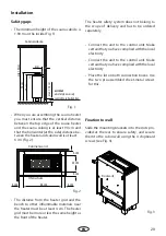
Using the above-mentioned wiring diagram 

and the information on the wiring circuit ad-

hered to the respective control system, your 

electrician will be able to connect the system 

without further instructions.

Please note that, for safety reasons, power ca-

bles may not be laid visibly on the interior walls 

of the cabin. Most sauna cabins have empty 

ducts fitted into the wall element with the air 

intake.
If no empty ducts are available in your cabin, 

drill a sufficiently sized hole in the cabin wall 

directly next to the place where the cable exits 

the sauna heater and guide this cable outside 

through the hole to the control unit. The cable, 

and all other connecting cables (mains power 

cables and cabin lighting), should be installed 

 Caution!

Dear Customer, 
In compliance with the valid regulations, 
only certified electricians may connect the 
sauna heater and the sauna control system 
to the mains power supply. 
Please note that you must provide a copy 
of the invoice from the electrical company 
who installed the sauna in case of a war-
ranty claim.
To preserve the right of a warranty claim, 
only original spare parts of the manufac-
turer may be used.

in installation ducts or also be protected against 

damage on the outside of the cabin e.g. by lay-

ing them in installation pipes or attaching wood 

cover strips.
The sauna heater, when made use of time pre-

set and remote control*, may only be used with 

an appropriate cover protection or any other 

safety device.

*Remote control – means settings, switching, control 

and adjustment of the sauna control unit by means of 

commands transmitted from a remote location beyond 

sight distance using telecommunication, wire- or wire-

less signal transmission systems, network and similar 

systems. (this also includes timers) (from EN 60335-1)

Summary of Contents for Bi-O Gracil

Page 1: ...INNOVATIVE SAUNA TECH NOLOGY IPx4 Made in Germany EOS Bi O Gracil Druck Nr 29344977 10 21 D Montage und Gebrauchsanweisung Assembly and operating instruction Saunaofen Sauna Heater EN...

Page 2: ...2 D...

Page 3: ...Lieferumfang 9 Technische Daten 9 Anschlussbeispiel einer Saunaanlage 10 Montage 11 Mindestabst nde 11 Wandsicherung 11 Bodensicherung 12 Finnischer Saunabetrieb 13 Betrieb mit Verdampfer 14 Optionale...

Page 4: ...sich an die Firma die Sie beliefert hat Beachten Sie dass Sie ein optimales Saunaklima nur dann erreichen wenn die Kabine mit ihrer Zuluft und Abluft der Saunaofen und das Steu erger t aufeinander ab...

Page 5: ...t d rfen nur in Saunakabinen aus geeignetem harzar men und unbehandeltem Material z B Nordische Fichte verwendet werden In der Saunakabine darf nur ein Saunao fen mit der erforderlichen Heizleistung...

Page 6: ...le Anschlussleitungen die im Inne ren der Kabine verlegt werden m ssen Silikonleitungen und f r eine Umge bungstemperatur von mindestens 170 C geeignet sein Werden als Anschlusslei tung einadrige Leit...

Page 7: ...er Reinigung von scharfkan tigen Komponenten sind entsprechende Eigenschutzma nahmen zu treffen Sauna fen mit Standmontage sind bau seitig gegen kippen zu sichern Achtung Aufgusswasserimmernur ber dem...

Page 8: ...ter muss au erhalb der Saunakabine angebracht sein und darf sich nicht au er Kraft setzen lassen In ffentlichen Saunen muss die Betriebs dauer des Saunaofens so begrenzt sein dass innerhalb von 24 Stu...

Page 9: ...ohne Steine undVerpackung 26 5 kg 27 kg 27 5 kg Ger tema e HxBxT 76 x 56 x 25 cm Steinf llung 20 kg nicht im Lieferumfang enthalten Verdampferleistung 0 75 kW Verdampfervolumen 2 l LSG erforderlich ne...

Page 10: ...de Sensor Sensorbus Saunabus reserviert 400 V 3N AC Netz Mains R seau 3x16A N PE Gr gn ge 750 W Verdampfer sw br bl Wb Wm Verdampfer Achtung Schlie en Sie Immer den Neutralleiter N des Saunaofens an U...

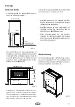
Page 11: ...es rt lichen EVU und des VDE beachten Beide Anschlussk sten mit den entspre chenden Deckel verschlie en Verwenden Sie hierzu jeweils die zwei bereits vormon tierten Blechschrauben Die Befestigungswink...

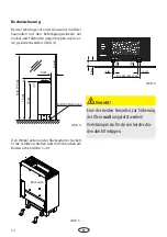
Page 12: ...esichert werden Abb 4 Den Winkel unten an der R ckseite des Sockels in die Schlitze schieben und mit Schrauben am Boden sichern Abb 5 6 Bodenbefestigung R ckseite Bodensicherung Abb 5 min 29 6 max 30...

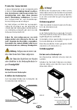
Page 13: ...z B Literbecher o Verbr hungsgefahr Bef llen des Verdampfers Zum manuellen Bef llen des Verdampfers die Verdampferschale abnehmen Finnischer Saunabetrieb In dieser Betriebsform ist der Verdampfer nich...

Page 14: ...bitte durch und bef llen Sie diesen anschlie end mit frischem Wasser Im Rahmen von Serviceeins tzen und War tungen sind alle wasserf hrende Bauteile und Verbindungen auf Undichtigkeiten zu pr fen Die...

Page 15: ...tkalkt werden Geben Sie hierzu Entkalker f r Haushaltsger te der auch f r Aluminiumgef e tauglich ist nach Angaben des Herstellers dem Wasser im Verdampfer bei Das Wasser Entkalkergemisch ca 10 Minute...

Page 16: ...des FWA01 angegebenen Standardeinbaulage nicht am Saunaofen sondern wie in der Abbildung an einem benachbarten Kabinenelement montiert werden Achten Sie auf die richtige Einbauh he Eine falsche H he...

Page 17: ...ieder ausreichend erhitzt Wir empfehlen im gewerblichen Bereich bei t glicher Nutzung die Steine alle 2 3 Monate zu berpr fen und neu aufzulegen ImprivatenBereichsolltenSiedieSteineminde stens 1 Mal p...

Page 18: ...esen FI Schalter ab gesichert werden Nach dem heutigen Stand der Technik ist es nicht sinnvoll dampfdichte Rohrheizk rper f r Sauna fen einzusetzen Es kann vorkommen dass die Magnesiumoxidf llung der...

Page 19: ...ycling Bitte diese Adresse zusammen mit der Montageanwei sung gut aufbewahren Damit wir Ihre Fragen schnell und kompetent beantwor ten k nnen geben Sie uns immer die auf dem Typen schild vermerkten Da...

Page 20: ...kte sind f r den St ckgut versand Palette konzipiert Wir weisen an dieser Stelle ausdr cklich darauf hin dass unsereVerpackungen nicht f r den Einzelversand per Paketdienst geeignet sind F r Sch den d...

Page 21: ...pe 27 Technical data 27 Connection example 28 Installation 29 Minimum distances 29 Wall fixation 30 Dry sauna mode 31 Humid sauna model 31 Operation with vaporizer 32 Vaporizer maintenance descaling 3...

Page 22: ...tact the company that shipped the goods Please note that you will only be able to achieve anoptimumsaunaclimateifthecabinwithitsair intake and ventilation the sauna heater and the control unit are ali...

Page 23: ...eater with the appropriate power output may be installed in the sau na cabin Please provide air intake and vent open ings in each sauna cabin The air intakes must always be positioned behind the sauna...

Page 24: ...e suitable cabin size in rela tion to the power input in kW When installing the sauna heater please ensure that the vertical clearance be tween the sauna heater upper edge and the sauna ceiling is mai...

Page 25: ...ized hole in the cabin wall directly next to the place where the cable exits the sauna heater and guide this cable outside through the hole to the control unit The cable and all other connecting cable...

Page 26: ...n the sauna control units The timer must be moun ted outside of the sauna cabin and may not be overridden The operation time of a public sauna must be limited so that the heating elements are withoutp...

Page 27: ...s and packing 26 5 kg 27 kg 27 5 kg Dimensions H xW x D 76 x 56 x 25 cm Stone volume 20 kg stones not inlcuded Vaporizer output 0 75 kW Vaporizer tank volume 2 l Power extension not needed Suitable co...

Page 28: ...3 4 S1 S1 N STB Saunasteuerger t Control unit Bo tier de commande Sensor Sensorbus Saunabus reserviert 400 V 3N AC Netz Mains R seau 3x16A N PE Gr gn ge 750 W Verdampfer sw br bl Wb Wm Vaporizer U V...

Page 29: ...that you have complied with the local electricity Place the lid on both connection boxes Use the two pre assembled sheet metal screws for this Slide the mounting brackets into the slots pro vided at t...

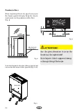
Page 30: ...the floor Fig 4 Push the bracket in the slits of the pedestal and secure it with screws on the ground Fig 5 6 Attachement to the base R ckseite Fixation to floor Fig 5 min 29 6 max 30 cm 2 cm 2 cm 1 c...

Page 31: ...er Remove the evaporator bowl to fill the evapo rator manually Humid sauna operation only by models with vaporizer Attention Always pour the water over the stones and not over other parts of the heate...

Page 32: ...eration a buzzing signal indi cates the water shortage To continue your sauna session you have to refill the tank after a 5 minutes stop of the sauna control or after switching to Finnish dry sauna fo...

Page 33: ...regular basis To descale the vaporizer add the de scaling liquid descalers for household appliances are generally suitable which is suitable for alumin ium to the water in the vaporizer in accordance...

Page 34: ...stallation position given in the manual of the FWA01 not on the sauna heater but as shown in Fig on an adjacent cabin element Make sure to observe the correct installation height Incorrect height may...

Page 35: ...By daily commercial use we recommend to check the condition of sauna stones every 2 3 months and to reshuffle them By home use the sauna stones need to be checked and reshuffled at least once per year...

Page 36: ...other electrical units will be protected by this ELCB Under current manufacturing technology it is not reasonable to use heating elements for sau na heaters which do not collect moisture from the sur...

Page 37: ...your questions quickly and compe tently please provide the information printed on the type shield including the model item no and serial no in all inquiries Equipment commissioning date ______________...

Page 38: ...roducts is designed for the ship ping of individually packed goods pallet We expressly point out that our packaging is not suitable for individual shipments via parcel post The manufacturer shall acce...

Reviews: