Envision R-410A Residential Installation Manual Download Page 17

16

ENVISION CONSOLE INSTALLATION MANUAL

System Cleaning and Flushing

Cleaning and Flushing

Prior to start up of any heat pump, the water circulating system must be 
cleaned and flushed of all dirt and debris.

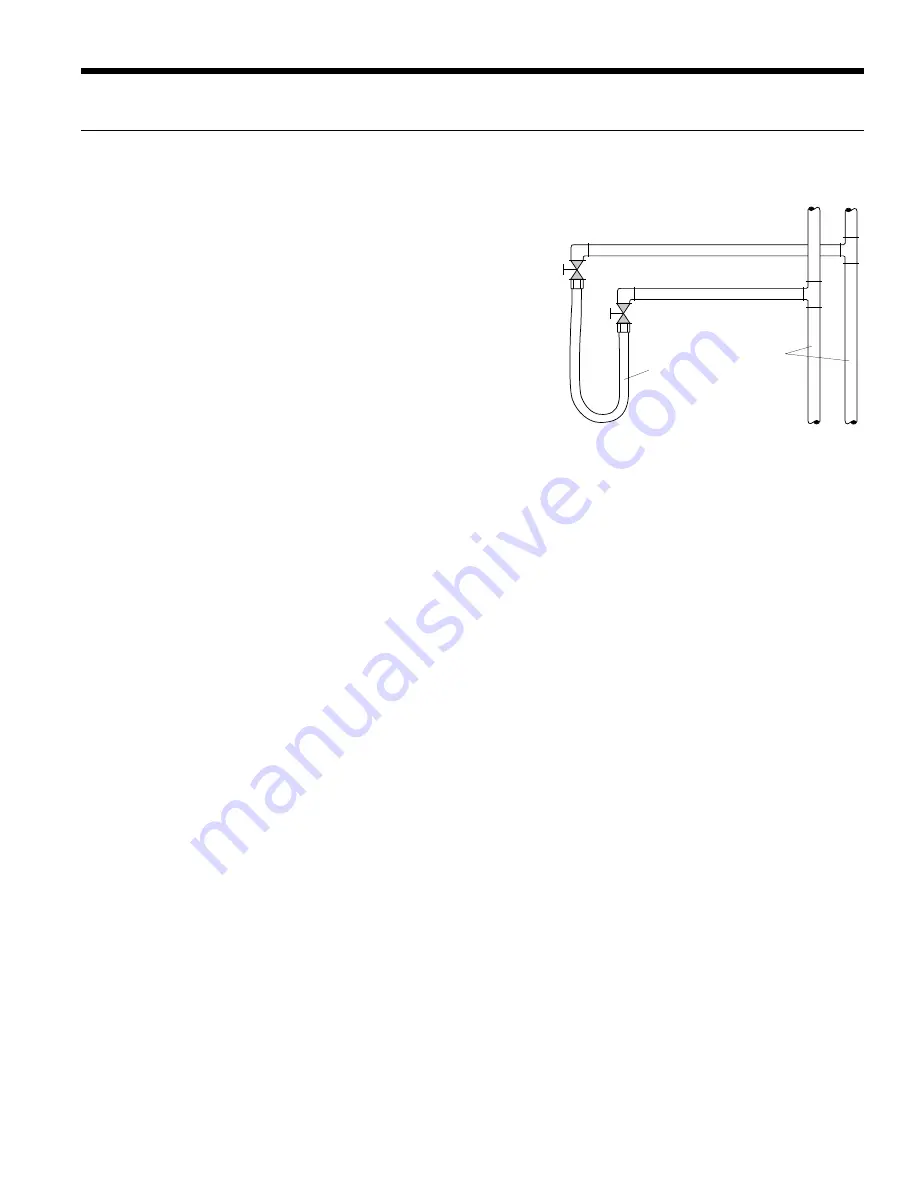
If the system is equipped with water shutoff valves, the supply and 
return runouts must be connected together at each unit location (This 
will prevent the introduction of dirt into the unit,  see Figure 7).  The 
system should be filled at the water make-up connection with all air 
vents open.  After filling, vents should be closed.

The contractor should start the main circulator with the pressure reduc-
ing valve makeup open.  Vents should be checked in sequence to bleed 
off any trapped air and to verify circulation through all components of 
the system.

As water circulates through the system, the contractor should check 
and repair any leaks found in the piping system.  Drain(s) at the lowest 
point(s) in the system should be opened for initial flush and blowdown, making sure water fill valves are set at the same 
rate.  Check the pressure gauge at the pump suction and manually adjust the make-up water valve to hold the same posi-
tive pressure both before and after opening the drain valves.  Flushing should continue for at least two hours, or longer if 
required, until drain water is clean and clear.

The supplemental heater and/or circulator pump, if used, should be shut off.  All drains and vents should be opened to 
completely drain the system.  Short-circuited supply and return runouts should now be connected to the unit supply and 
return connections.

Refill the system with clean water.  Test the system water for acidity and treat as required to leave the water slightly alkaline 
(pH 7.5 to 8.5).  The specified percentage of antifreeze may also be added at this time.  Use commercial grade antifreeze 
designed for HVAC systems only.  Environol™ brand antifreeze is recommended..

Once the system has been filled with clean water and antifreeze (if used), precautions should be taken to protect the sys-
tem from dirty water conditions.  Dirty water will result in system-wide degradation of performance, and solids may clog 
valves, strainers, flow regulators, etc.  Additionally, the heat exchanger may become clogged which reduces compressor 
service life and can cause premature unit failure.

In boiler/tower application, set the loop control panel set points to desired temperatures.  Supply power to all motors and 
start the circulating pumps.  After full flow has been established through all components including the heat rejector (re-
gardless of season),  air vented and loop temperatures stabilized, each of the units will be ready for check, test and start up 
and for air and water balancing.

Ground Source Loop System Checkout

Once piping is completed between the unit pumping system and ground loop, final purging and charging of the loop is 
needed.  A high pressure pump is needed to achieve adequate flow velocity in the loop to purge air and dirt particles from 
the loop itself.  Antifreeze solution is used in most areas to prevent freezing.  Flush the system adequately to remove as 
much air as possible; then pressurize the loop to a static pressure of 40-50 PSI (summer) or 50-75 PSI (winter).  This is 
normally adequate for good system operation.  Loop static pressure may decrease soon after initial installation, due to pipe 
expansion and loop temperature change.  Running the unit for at least 30 minutes after the system has been completely 
purged of air will allow for the “break-in” period.  It may be necessary to adjust static loop pressure (by adding water) after 
the unit has run for the first time.  Loop static pressure will also fluctuate with the seasons.  Pressures will be higher in the 
winter months than during the cooling season.  This fluctuation is normal and should be considered when charging the 
system initially.

Insure the pump provides adequate flow through the unit by checking pressure drop across the heat exchanger.   
Usually 2.25-3.0 GPM of flow per ton of cooling capacity is recommended in earth loop applications.

Return Runout

Supply Runout

Mains

Rubber Hose

Runouts Initially

Connected Together

Figure 7:  Flushing with Water 
Shutoff Valve Equipped Systems

Summary of Contents for R-410A Residential

Page 1: ...formation Water Piping Connections Electrical Startup Procedures Troubleshooting Preventive Maintenance Envision Console Installation Manual Geothermal Water Source Heat Pumps R 410A Refrigerant 0 75...

Page 2: ......

Page 3: ...Ground Water Systems 17 Electrical Connections 18 Auxiliary Heat Ratings 18 Unit Electrical Data 19 Fan Performance Table 19 Wiring Schematics 20 24 Envision Console Controls 25 39 Unit Startup Notes...

Page 4: ...Range 3 No Coating Extended Range Piping Option 4 No Coating Standard Range L Left R Right N A with chassis only Sound Kit A None Voltage B Blanket 0 208 230 60 1 2 265 60 1 Auxilliary Electric heat...

Page 5: ...the packag ing if necessary Units in question should also be internally inspected If any damage is noted the carrier should make the proper notation on the delivery receipt acknowledging the damage Wa...

Page 6: ...3 3 49 1 11 8 4 3 cm 127 0 31 1 65 2 23 4 88 9 15 6 8 3 124 7 29 8 10 9 09 12 15 18 4 0 5 7 8 1 3 2 6 47 B3 0 193B 47 B3 0 193B 756B 3BC B 4 B 34B 3BC 23B 7 0 BE7AB 3FB3 232 B 0 0 19 2 4 B6 C B7 B 0...

Page 7: ...1 2 5 49 1 11 8 4 3 cm 127 0 32 0 73 9 23 4 88 9 15 6 6 4 124 7 29 8 10 9 09 12 15 18 3 D3 AB71 AB 7 4 0 93 B 0 2 3 13 0 93 3253 4 35 A A6 E 6 7 8 1 4 3 2 5 0 756B 3BC B 4 B 34B 3BC 23B 7 0 BE7AB 3FB3...

Page 8: ...6 6 1 124 7 30 5 10 9 in 55 0 12 6 29 1 9 2 35 0 6 1 2 5 54 1 11 8 4 3 cm 139 7 32 0 73 9 23 4 88 9 15 6 6 4 137 4 29 8 10 9 09 12 15 18 47 B3 0 193B 47 B3 0 193B 2 3 1 6 7 8 4 0 5 0 756B 3BC B 4 B 3...

Page 9: ...2 4 1 7BG 0 B6 A723A 3 31B 71 63 B 23 0 7 3 3AA AE7B16 B7 4 B7 AE7B16 B7 0 19 B3 3 C7 32 4 2 3 7 AB B7 CBA723 7 2 3 B7 473 2 7 AB 32 E D B 53 B3 7 A 4F 3 B3 E AB B B7 A G B7 4CA32 4CA32 27A1 31B B7 0...

Page 10: ...47 B3 1 B 3 1 23 A B3 2 7 1 31B7 E B3 CB 4 B E B3 7 4 B B7 0 19 B3 1 3AA 113AA 3 2 3 3 7 5 1 0 E3 113AA 3 1 3AA 113AA 3 47 B3 1 B 3 1 23 A B3 2 7 1 31B7 E B3 CB 4 B E B3 7 4 B B7 0 19 B3 1 3AA 113AA 3...

Page 11: ...D3A B7 6 A3 97BA 1 23 A B3 2 7 1 31B7 47 B3 6 2G 0 F B7 3 31B 71 63 B B7 0 19 B3 3 C7 32 4 2 3 7 AB B7 CBA723 7 2 3 B7 473 2 7 AB 32 1 B 3 3 D3 4 113AA B 1 B 0 F 2 3 44 AE7B16 1 3AA 113AA 3 3 D32 4 1...

Page 12: ...47 B3 1 B 3 1 23 A B3 2 7 1 31B7 E B3 CB 4 B E B3 7 4 B B7 0 19 B3 1 3AA 113AA 3 2 3 3 7 5 1 0 E3 113AA 3 1 3AA 113AA 3 47 B3 1 B 3 1 23 A B3 2 7 1 31B7 E B3 CB 4 B E B3 7 4 B B7 0 19 B3 1 3AA 113AA...

Page 13: ...ate mounting height is increased by the thickness of the shims used Position backplate in desired equipment location To further reduce the operating sound level of the unit 1 8 inch thick rubber matti...

Page 14: ...o the units An air vent must be installed in the water distribution system The supply and return water piping should be run through the wall or floor penetration and terminate with a ball valve The pi...

Page 15: ...should be installed on both the supply and return water lines of the unit Flow control valves should be installed on the water discharge line It is recommended that P T ports be installed on the suppl...

Page 16: ...inet repositioning pieces 4 1 2 and 3 into the locations directly opposite the original positions Secure by replacing mounting brackets Note Be sure that louvers on the grille assembly are facing the...

Page 17: ...rotect the sys tem from dirty water conditions Dirty water will result in system wide degradation of performance and solids may clog valves strainers flow regulators etc Additionally the heat exchange...

Page 18: ...pliance in your area Note For open loop groundwater systems or systems that do not contain an antifreeze solution set SW1 Switch 2 to the WELL position Refer to the Dip Switch Field Selection table Sl...

Page 19: ...L S X2 X1 W2 Field Connections Unit Connections 24 VAC COMMON COMPRESSOR REVERSING VALVE FAN LOCKOUT SIGNAL SHUTDOWN NIGHT SETBACK LOAD SHED Requires common connections or 24 VAC for activation Red Bl...

Page 20: ...500 fpm by 0 16 in wg Unit Electrical Data Model Rated Voltage Voltage Min Max Compressor Fan Motor FLA Total Unit FLA Min Circ Amp Max Fuse HACR MCC RLA LRA 09 208 230 60 1 197 253 6 4 4 1 21 0 0 50...

Page 21: ...White 20 Orange 14 Orange 21 Black 29 Red 30 Black Black 12 White 18 Red 11 Red 19 Red 17 24 V Accessory 24VAC Shutdown Red 15 Red 16 NOTE 1 T ST CC Compressor Contactor HP High Pressure Switch LP Low...

Page 22: ...ack 27 RB 4 2 5 Red EH T2 T1 L2 White White L1 EH Normal RV DT ON OFF Damper Sw Damper Motor D Fan Mode Sw 4 5 2 E1 E1 AQ Blk Wht 24 Blk Wht 23 Black 22 White 18 Blue T6 NOTE 2 3 1 RB 3 1 Black 37 Blu...

Page 23: ...ated ON Current fault or Output display mode activated Normal Standard timings Well Open loop freeze sensing setting 30 F Normal Unit status display Normal Standard thermostat operation Normal Standar...

Page 24: ...g information for specific thermostat hookup instructions Red Black 25 RB Gray 42 White 28 Black 29 Red 30 Damper Motor Off On DAMPER MODE DT D Blue Wht 35 MV Black 31 Red 32 Handi Box Ground Lug Unit...

Page 25: ...eeze protection Field Zone Sensor Wiring 3 Acc 1 output is cycled with the compressor 4 Acc 2 output is cycled with the fan 5 R C Y1 O and G inputs are for use with a wall mounted thermostat A23 A13 A...

Page 26: ...tional Medium User Interface MUI can be used as a field service tool Standalone Unit Mounted Digital Dial Sensor Remote Mounted Standard Thermostat Remote Mounted Sensor FX10 w N2 FX10 Control functio...

Page 27: ...he Versatec microprocessor board provides control of the entire unit as well as outputs for status modes faults and diagnostics The control system is a microprocessor based control board that is locat...

Page 28: ...e sensing fault bypass delay 2 minutes Power on delay 5 minutes Normal Control Timing Operational Logic Blower off delay 5 seconds Compressor on delay 2 seconds Short cycle delay 15 seconds Miniumum c...

Page 29: ...r Coil Low Temperature Freeze Sensing Condensate overflow sensing Lockout mode control Emergency shutdown mode Random start and short cycle protection Short Cycle Protection Allows a minimum compresso...

Page 30: ...talled emergency heat in the event that the compressor is locked out This input can also be commanded on from a BAS as needed An alarm history can be viewed through the MUI and will be held in memory...

Page 31: ...or becomes unreliable at any time compressor operation will immediately be suspended until the problem is corrected This should be displayed as an alarm on the BAS and the MUI This alarm will be repor...

Page 32: ...capacity for a minimum of 30 seconds before the full capacity com pressor output can be enabled During low capacity compressor operation the ECM2 blower will operate in medium speed and will operate...

Page 33: ...arm History Reporting If a fault occurs the fault will be recorded in history for display on the medium user interface in the History Menu Each fault type will be displayed in the history menu with a...

Page 34: ...ter to Air Welcome Info Status Temps Outputs Settings Maint Alarms Alm History WFI Envision Series PROFXENV XX 3 8 07 Info Run Mode Auto Eff Occup y Occ Y1 Input OFF Y2 Input OFF G Input OFF O Input O...

Page 35: ...p 0 Bad Sensor 0 Alm History NOTE This FX10 application implements an alarm history which is reset only by cycling power This history shows on the Alm History page Any alarm showing 4 events has occur...

Page 36: ...ting Freeze Sensing Temperature Value Read Only ADF 40 nvoHtgFrzSetpt Heating Freeze Sensing Temperature Setpoint Value Read Only ADF 41 nvoAlarms Alarms Enumerated 0 no alarms 1 condensate alarm 2 Co...

Page 37: ...Compressor low Suction Pressure alarm 4 Freeze sensing alarm 8 Faulty Freeze Sensor alarm 9 Loss of Charge Read Only nvoPWMOut SNVT_volt 44 ECM PWM Control signal value Read Only nvoECMOvrd SNVT_volt...

Page 38: ...9 Loss of Charge Read Only Analog Input 0 8 Present_Value 85 WFI ECM Cmd Output Present_Value ECM PWM Control signal value Read Only Analog Output 1 2 Present_Value 85 WFI ECM Fan Ovrd Present_Value...

Page 39: ...network to send space temperature values to the heat pump controller volatile these will supersede any temperature sensor connected to the space temperature Analog Input Analog Value Type 2 2 1 Occupi...

Page 40: ...k command equivalent of a thermostatic G call 14 3 Compressor Cmd Y1 Write allows a network command equivalent of a thermostatic Y1 call 14 4 Compressor Cmd Y2 Write allows a network command equivalen...

Page 41: ...able in five models with equipment rated fuses to provide addi tional circuit protection The fuses are panel mounted to allow easy inspection and removal without removing the cover on the disconnect C...

Page 42: ...ng setpoint must be set below room temperature 3 Be sure that the compressor and water control valve or loop pump s are activated 4 Verify that the water flow rate is correct by measuring the pressure...

Page 43: ...rmance based on entering air temperatures of 80 F DB 67 F WB Heating performance based on entering air temperature of 70 F DB Operating Limits F C F C Air Limits Min Ambient Air 45 7 2 45 7 2 Rated Am...

Page 44: ...85 for water antifreeze x T Note DO NOT hook up pressure gauges unless there appears to be a performance problem Line Voltage Loop Open Unit Amp Draw Closed COAX SOURCE HEATING CYCLE ANALYSIS EXPANSIO...

Page 45: ...09 1 2 1 0 0 9 0 8 0 7 0 6 1 8 2 3 2 2 2 0 1 9 1 8 2 5 3 8 3 7 3 5 3 3 3 1 12 1 5 0 9 0 8 0 7 0 6 0 5 2 3 1 7 1 5 1 4 1 3 1 1 3 5 3 0 2 7 2 5 2 4 2 2 15 2 0 1 7 1 6 1 5 1 4 1 3 3 0 3 3 3 2 3 0 2 9 2...

Page 46: ...ssure Note On open loop systems if the installation is in an area with a known high mineral content 125 PPM or greater in the water it is best to establish with the owner a periodic maintenance schedu...

Page 47: ......

Page 48: ...nace International Inc 9000 Conservation Way Fort Wayne IN 46809 www waterfurnace com WaterFurnace International Inc 9000 Conservation Way Fort Wayne IN 46809 9794 WaterFurnace has a policy of continu...

Reviews: