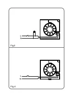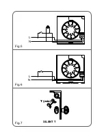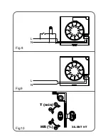
Once the cable has been introduced proceed using the electrical wiring diagram
applicable to the selected model.
. SILENT-100 S DESIGN
This model uses the following diagrams:
Fig.3: Fan operating through a light switch.
Fig.4: Fan operating through an independent switch.
. SILENT-100 P DESIGN
Model fitted with on/off pullcord switch uses the following diagrams:
Fig.3: Fan operating through a light switch.
Fig.4: Fan operating through an independent switch.
. SILENT-100 T DESIGN
This model is provided with an adjustable over-run timer. The timer allows the fan to
continue to operate for the selected period after the switch has been turned off
(fig.6).
The model is provided with 4 positions to adjust the electronic timer: Fig.5 shows
how to connect the fan with timer utilising the same switch as for the lighting circuit.
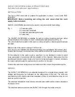
To set the timer, turn the potentiometer on the printed circuit board as (fig. 7):
- To reduce the "run on" time, turn anticlockwise (min. 1 minute)
- To increase the "run on" time, turn clockwise (max: 30 minutes).
. SILENT-100 HT DESIGN
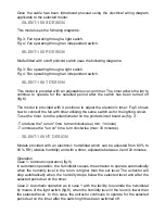
Models provided with an electronic humidistat which can be adjusted from 60% to
90 % RH (relative humidity) and with a timer, adjustable between 2 and 20 minutes.
Operation
Case 1: Automatic operation (fig.9)
In automatic operation, the humidistat causes the extractor to operate automatically
when the humidity level in the room is higher than the set level. The extractor will
stop automatically when the humidity drops below the selected level and after the
selected period set on the timer.
Case 2: Automatic operation as in case 1 with the facility to override the humidistat
by means of the light switch (fig.8), when the humidity level in the room is lower than
the selected level. In this case, the extractor continues to operate for the selected
period set on the timer after the switch light has been switched off.


