


FORM ET145.18-IOM1 (115)
ENVIRO-TEC
20
7.
SUPPLY AIR DUCTWORK
Installer must ensure there is no direct contact
between cabinet sheet metal parts and drywall
enclosure. This includes return air and supply air
flanges. Failure to follow these instructions will
negatively affect unit sound performance.
A.
Horizontal Supply Air
A 2” duct flange (field provided) may be required to eliminate
supply air recirculation when shallow profile, single deflection
supply grilles are installed at the cabinet discharge openings. If
the discharge from the cabinet is not ducted completely into
the conditioned space, air can recirculate into the return air
opening from the space inside the drywall enclosure.
JCI supplied grilles shall have a clearance of ¼” around the
perimeter in order to fit inside the unit supply flange. Other
grille manufacturers could have different clearances and
should be verified.
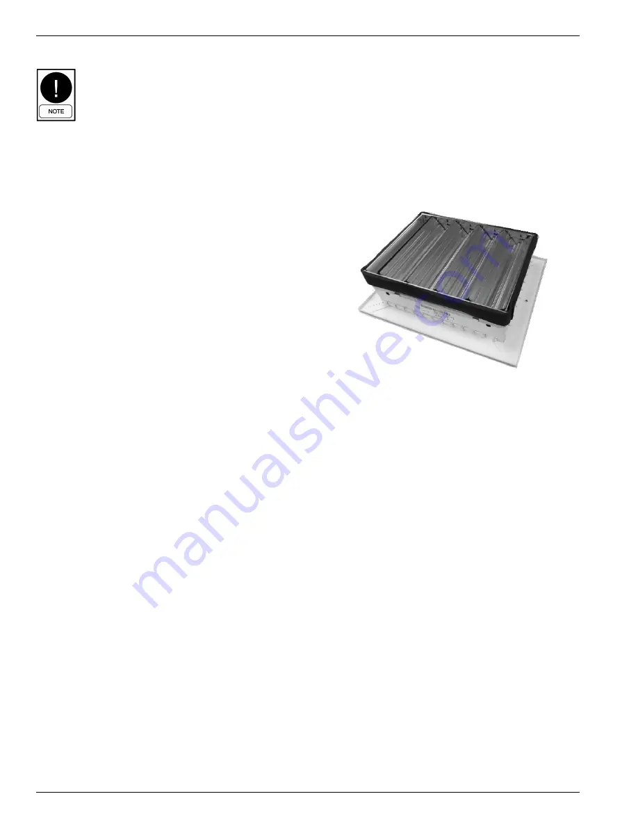
Field supplied gasket must be applied accordingly in order to
prevent air recirculation and vibration transfer when supply
grilles are mounted to unit supply opening. When mounting
supply grilles with optional volume damper directly to cabinet
supply flange, the volume damper will fit inside the cabinet
supply flange. It is recommended to apply 1/8” neoprene tape
around the perimeter the volume damper prior to inserting into
the supply opening. See Figure 11 for an example. This will
assist in reducing noise transmission and air recirculation into
unit closet
For ducted openings connect the unit supply opening to the
supply ductwork using a watertight flexible duct connector.
This will minimize the transmission of operating sounds
through the supply ductwork. Elbows with turning vanes or
splitters are recommended to minimize air noise due to
turbulence and to help reduce static pressure.
B.
Top Discharge Supply Air
Units that are installed with a top discharge should be
connected to the supply ductwork with a watertight flexible
connector. This will minimize the transmission of operating
sounds through the supply ductwork. Elbows with turning
vanes or splitters are recommended to minimize air noise due
to turbulence and to help reduce static pressure.
For information on available unit horizontal and top supply
openings see Table 4 on the following page. Recommended
face velocity at the outlet supply grille is 300-500 FPM. Table
4 gives face velocity at the unit supply openings in relation to
Table 3. To calculate the face velocity at the supply grille, take
the FPM from Table 4 and divide by the supply grille free area
factor.
FIGURE 10 – Supply Grille with Volume Damper and 1/8”
Neoprene Tape Applied To Perimeter
Summary of Contents for VB09-36
Page 6: ...FORM ET145 18 IOM1 115 ENVIRO TEC 6 FIGURE 1 Cabinet Chassis Model Nomenclature ...
Page 7: ...FORM ET145 18 IOM1 115 ENVIRO TEC 7 ...
Page 34: ...FORM ET145 18 IOM1 115 ENVIRO TEC 34 APPENDIX PSC MOTOR WIRING DIAGRAM ...
Page 35: ...FORM ET145 18 IOM1 115 ENVIRO TEC 35 ECM WIRING DIAGRAM ...
Page 36: ...FORM ET145 18 IOM1 115 ENVIRO TEC 36 CONTINUOUS FAN WITH ECM WIRING DIAGRAM ...
Page 37: ...FORM ET145 18 IOM1 115 ENVIRO TEC 37 MOTORIZED DAMPER ECM WIRING DIAGRAM ...