background image

29

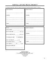
Installation Data Sheet

The following information must be recorded by the installer for warranty purposes and future reference.

NAME OF OWNER:

_________________________________________

ADDRESS:

_________________________________________

_________________________________________

_________________________________________

PHONE:___________________________________

NAME OF DEALER:

_________________________________________

ADDRESS:

_________________________________________

_________________________________________

_________________________________________

PHONE:___________________________________

MODEL:___________________________________

SERIAL NUMBER:___________________________

DATE OF PURCHASE: _____________  

(dd/mm/yyyy)

DATE OF INSTALLATION:___________

(dd/mm/yyyy)

� 

NATURAL GAS (NAT)        

� 

PROPANE(LPG)

INLET GAS PRESSURE:_________in wc

MAIN BURNER ORIFICE:__________# DMS

PILOT ORIFICE #_________OR________in diam.

INSTALLER’S SIGNATURE:

_________________________________________

NAME OF INSTALLER:

_________________________________________

ADDRESS:

_________________________________________

_________________________________________

_________________________________________

PHONE:___________________________________

MANUFACTURED BY:

SHERWOOD INDUSTRIES LTD. 

6782 OLDFIELD RD.  SAANICHTON, BC, CANADA  V8M 2A3

www.envirofire.biz

June 14, 2004

C-10235

Summary of Contents for Accent 20 BV

Page 1: ...ation and service must be performed by a qualified installer service agency or the gas supplier 50 304 Accent 20 BV This appliance is only for use with the type of gas indicated on the rating plate This appliance is not convertible for use with other gases unless a certified kit is used FOR YOUR SAFETY Do not store or use gasoline or other flammable vapours and liquids in the vicinity of this or a...

Page 2: ...s to the current CAN CGA B149 installation code Canada or National Fuel Gas Code ANSI Z223 1 2 USA To prevent injury do not allow anyone who is unfamiliar with the stove to operate it To prevent injury if the pilot or pilot and burners have gone out on their own open the glass door and wait 5 minutes to air out before attempting to re light the stove Always keep the area around these appliances cl...

Page 3: ... For Installation 12 Assembling And Installation Instructions 12 Venting 13 Venting Fireplace Inserts 13 Gas Line Connection 14 Electrical System 15 Removing and Installing The Blower 15 Secondary Installation 16 Log Set and Ember Installation 16 Removing And Installing The Brick Panels 18 Cast Iron Surround Panel Extension Trim Kit 19 Trouble Shooting 20 Parts List Cast 21 Parts Diagram Cast 23 P...

Page 4: ...2 17 M91 GAS FIRED APPLIANCES FOR HIGH ALTITUDES CSA P 4 1 02 TESTING METHOD FOR MEASURING ANNUAL FIREPLACE EFFICIENCY This ENVIRO Accent 20 BV Fireplace Has been certified for use with either natural or propane gases See rating label Is not for use with solid fuels Is approved for bedroom or bed sitting room IN CANADA must be installed with a listed wall thermostat IN USA see current ANSI Z223 1 ...

Page 5: ... do not require cutting bending or breaking from the factory built fireplace in order to allow the insert to fit Sherwood Industries Ltd Policy Intretek has approved listed factory built fireplaces as a certified zero clearance kit provided that the following conditions have been met 1 The removal of any part will not weaken the stuctural integrity of the factory built fireplace 2 The factory buil...

Page 6: ...um firebox size Width 27 656 mm Hieght 19 483 mm Depth 15 381 mm CLEARANCES TO COMBUSTIBLES You must maintain sufficient clearances for operation service and maintenance Mantle pillar to side of surround panel 2 51 mm Bottom of unit to 8 wide mantle 40 1016 mm Minimum non combustible surface in front of unit 8 203 mm CLEARANCES MUST BE SUFFICIENT TO ALLOW ACCESS FOR MAINTENANCE AND SERVICE RATING ...

Page 7: ...s for the thermocouple to cool 1 STOP Read the safety information above on this label 2 Turn the thermostat to the lowest setting 3 Turn off all electrical power to the appliance 4 Set the burner switch to the middle off position located on the top right side of the surround panel set 5 Depress pilot gas knob slightly and turn clockwise to the off position 6 Wait five 5 minutes to clear out any ga...

Page 8: ...pilot flame should be blue with little or no yellow on the tips The venting system must be periodically examined it is recommended the examination is done by a qualified agency OPENING THE DOOR 1 Turn unit off and wait until the appliance has cooled down 2 Open the lower louver panel 3 Use a 5 16 socket to undo the two bolts at the bottom corners of the door 4 Swing door out then lift up and out t...

Page 9: ... carefully as they are very fragile Gently remove all the embers and rock wool and place on a paper towel 3 Vacuum the bottom of the firebox thoroughly Carefully clean any dust off the logs and brick panels and remove any lint from the burner and pilot A clean 2 5 cm paint brush will work too At this time inspect the burner pan for cracking or severe warping If a problem is suspected contact the d...

Page 10: ...onto the back firewall Lift the control tray up on the left side and pull out Remove wire connector from firebox 6 Installation is the reverse When installing the log set refer to Secondary Installation Log Set and Ember Installation Caution Bleed lines before lighting and light pilot with door open ADJUSTING VENTURI AIR SETTINGS There is one venturi and one air shutter on this appliance The ventu...

Page 11: ...onversion kit Simply screw the new injector inside the pilot hood and reinstall the hood by placing the hood on the assembly line up the key way and snap into place Step 7 Remove the main burner orifice with a 1 2 inch deep socket Step 8 Install the new orifice supplied Be sure to put a bead of pipe thread sealant or approved Teflon tape on the orifice before installing into the burner assembly St...

Page 12: ... Slide the insert into the fireplace ensuring that the exhaust channel is located under the slide rails on the top of the fireplace insert 8 Re install the locating screw and tighten 9 To assemble the surround panel lay the panel face down on a soft flat surface and place the brass trim on the surround panel using the corner brackets to hold the trim to the surround panel 10 Connect the surround p...

Page 13: ...del can be vented with 3 aluminum or stainless steel flex vent and or certified Type B Gas Vent The flue collar of the appliance will fit inside a standard 3 vent and may be fastened directly to the vent Check periodically that the vent is unrestricted and an adequate draft is present when the unit is in operation VENTING FIREPLACE INSERTS WARNING Operation of this heater when not connected to a p...

Page 14: ... supply piping system during any pressure testing where the pressure exceeds 1 2 psig 3 45 kPa or the valve will be damaged The unit must be isolated from the gas supply piping system by closing its individual manual shut off valve during any pressure testing of the gas supply piping system at pressures equal to or less than 1 2 psig 3 45 kPa Always check for gas leaks with a soap and water soluti...

Page 15: ...lue Blue Blue Grey Grey Grey White White White White Orange Orange Orange Figure 10 Installation of the blower REMOVING AND INSTALLING THE BLOWER 1 Shut off gas supply to appliance and turn unit off 2 Open the door and gently remove the logs Remove the brick panel as per instructions in Secondary Installation Removing and Installing The Brick Panels 3 Remove the burner tray assembly by removing th...

Page 16: ... in place This points out the two 2 placement pins for the back log on the burner Figure 12 The first log to be placed is the back log it has two 2 placement pins Note The back log may fit tight against the back of the firebox Figure 13 The left log has two 2 placement pins Figure 12 First Stage Log Set Installation Figure 13 Second Stage Log Set Installation 16 logs come with placement pins notch...

Page 17: ...ramic fiber embers Place the embers irregularly around the burner Figure 16 Complete log set up with embers WARNINGS DO NOT pack this ember material as this could create an unsafe condition The pieces should be lightly placed so they don t block any of the burner ports DO NOT allow any of the embers to rest against the pilot assembly Caution Use only the type of ember material supplied with this f...

Page 18: ... or door as the unit will start to smoke and can irritate some people After the unit has gone through the first burn turn the unit off including the pilot let the unit cool then remove the glass door and clean it with a good gas fireplace glass cleaner available at your local ENVIRO dealer Maintenance Once a year the logs should be removed and checked for deterioration or large amounts of soot A s...

Page 19: ...kets and eight 1 4 bolts four on each side supplied with the extension INSTALL SURROUND PANEL EXTENSION TO THE BOTTOM Place the extension under the surround panel with the widest side facing up To bolt the extension onto the bottom the old mounting brackets on the panel have to be replaced with the new side mounting brackets and eight 1 4 bolts four on each side Secondary Installation CAST IRON SU...

Page 20: ...Burners will not remain lit Problem with thermopile circuit Check gas line pressure Check for flame impingement on thermopile If low see Pilot will not remain lit Check thermopile for minimum of 200 mV when burner is switched on Check wiring to thermostat for breaks Flame lifting Leak in vent pipe Check for leaks in vent connections Improper vent configuration Check vent configuration with manual ...

Page 21: ... Surround Panels Only Antique Chestnut 50 883 1 Surround Panels Top Piece Only Painted 50 416 1 Surround Panels Top Piece Only Diamond Black 50 417 1 Surround Panels Top Piece Only Inferno Red 50 418 1 Surround Panels Top Piece Only Pearl Grey 50 419 1 Surround Panels Top Piece Only Antique White 50 420 1 Surround Panels Top Piece Only Wedgewood Blue 50 421 1 Surround Panels Top Piece Only Westpor...

Page 22: ...und valve door or clip on Inferno Red 50 440 4 Front Only No glass surround valve door or clip on Pearl Grey 50 441 4 Front Only No glass surround valve door or clip on Wedgewood Blue 50 442 4 Front Only No glass surround valve door or clip on Westport Green 50 443 4 Front Only No glass surround valve door or clip on Antique Chestnut 50 879 5 Valve Access Door Painted 50 444 5 Valve Access Door An...

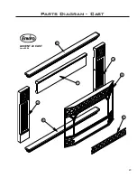
Page 23: ...23 Parts Diagram Cast ACCENT 20 CAST June 2004 2 1 6 3 6 4 5 ...

Page 24: ...104 9 Regular Surround Panel with Brass Trim EG20 120 10 Regular Trim Only Black 50 126 10 Regular Trim Only Brass 50 114 10 Regular Trim Only Nickel 50 138 11 Four Sided Surround Panel with Black Trim 50 106 11 Four Sided Surround Panel with Brass Trim EG20 130 12 Four Sided Trim Only Black 50 128 12 Four Sided Trim Only Brass 50 116 12 Four Sided Trim Only Nickel 50 140 13 Tapped Corner Bracket ...

Page 25: ...25 Parts Diagram Surround Panels Accent 20 Insert Surround Panel June 2004 10 9 7 8 11 12 14 13 ...

Page 26: ...3 22 Fan Mount EC 028 Wiring Harness Complete 3 Pieces EC 033 Wiring Harness Body EC 035 Wiring Harness Burner EC 036 Domestic Power Cord 115V EC 042 Heyco Strain Relief EC 044 Embers Coal Wool EC 046 Log Set with Embers EC 048 Insert Valve Access Door Magnets x 2 EC 050 23 Convection Blower 115V EC 069 NG Burner Control Assembly EG20 052 LP Burner Control Assembly EG20 054 24 3 X 3 8 Black Iron N...

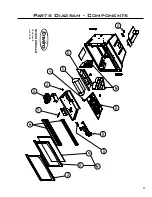
Page 27: ...27 Parts Diagram Components Accent 20 Insert Components June 2004 18 22 16 17 23 19 21 30 26 25 20 24 27 28 29 15 ...

Page 28: ...ereafter The paint on the Metal Brick Liner may peel This is due to the extreme conditions applied to the paint and is not covered under warranty Your dealer shall make all claims under this warranty in writing TO A MAXIMUM OF SEVEN YEARS WHEN FILING A WARRANTY CLAIM PLEASE COMPLETE THE FOLLOWING INFORMATION ON AN OFFICIAL WARRANTY CLAIM FORM To the Dealer Name address and telephone number of purc...

Page 29: ..._______________________________ MODEL ___________________________________ SERIAL NUMBER ___________________________ DATE OF PURCHASE _____________ dd mm yyyy DATE OF INSTALLATION ___________ dd mm yyyy NATURAL GAS NAT PROPANE LPG INLET GAS PRESSURE _________in wc MAIN BURNER ORIFICE __________ DMS PILOT ORIFICE _________OR________in diam INSTALLER S SIGNATURE ______________________________________...

Reviews: