


2
I n s t a l l a t i o n & O p e r a t i o n M a n u a l
Innovators in Clean Air Technology | www.envirco.com
MDR16
MAC 10
®
Remote Mount Fan Controller
APPLICATION
The MDR16 MAC10® Remote Mount Fan Filter Controller allows manual adjustment of industry standard 0-10VDC automation
signals to control up to 16 ENVIRCO ECM based FFUs. The MDR16 provides local or remote adjustment of the FFU output from
1% to 100% of the motor’s control range. A signal lamp on the control continuously flashes out the flow index. Therefore, other
instruments are not required to read the flow index (%). The MDR16 can be configured for 0-10VDC, a 2-10VDC or a 4-20mA
automation signals. If desired, the MDR16 also can be used for stand-alone manual control by internal jumper configuration.
Signal Lamp Feedback
The MDR16 green front panel lamp continuously indicates the flow index setting for the entire group of FFUs being controlled. After
a pause, the lamp flashes out the tens digit, then the units digit of a number between 1 and 99. Long flashes represent the tens digit
and short flashes represent the units digit. For example, a flow index of 23 flashes two longs, then three shorts. Two extra-long
flashes indicate a flow index of 0. An extra-long flash and ten short flashes indicate a flow index of 100. The lamp flashes the signal
that was present when the flash sequence started.
Operating Control Modes
The MDR support group control of up to 16 ECM based ENVIRCO FFUs in two different modes, including a pure manual mode and
a mode where the FFUs’ performance is slaved to an external automation control input.
Pure manual mode is a simple control capability that is enabled when internal
Jumper #3
named Manual Override is present.
With
Jumper #3
present, the front panel adjust screw is the only way to control the FFU performance index. With a small straight
screwdriver to turn the front panel accessible potentiometer, the user can adjust the FFU performance index up or down. The Signal
Lamp will provide real-time feedback of the performance index set-point.
Alternatively, if internal
Jumper #3
is not present, automatic mode is selected, and the potentiometer has different functions. In
automatic mode (no
Jumper #3
present), the potentiometer will control the FFUs’ performance when the automation signal is not
present. This feature allows adjustment of the FFUs on a new installation until automation is installed. Automation will finally start/
stop the motor five times, and LSO will be disabled. Turning the potentiometer always overrides any automation signal, manually
controlling the FFU for 15 minutes. Control reverts to any connected automation signal when the 15 minute adjust timer expires.
Cycling the power early will instantly reset to automatic mode if required.
There are two additional cases in automatic mode for the adjust function that are set by jumpers. In automatic, the potentiometer is used
to set the FFU default performance level when the automation signal is absent or the automation signal is outside its normal control range.
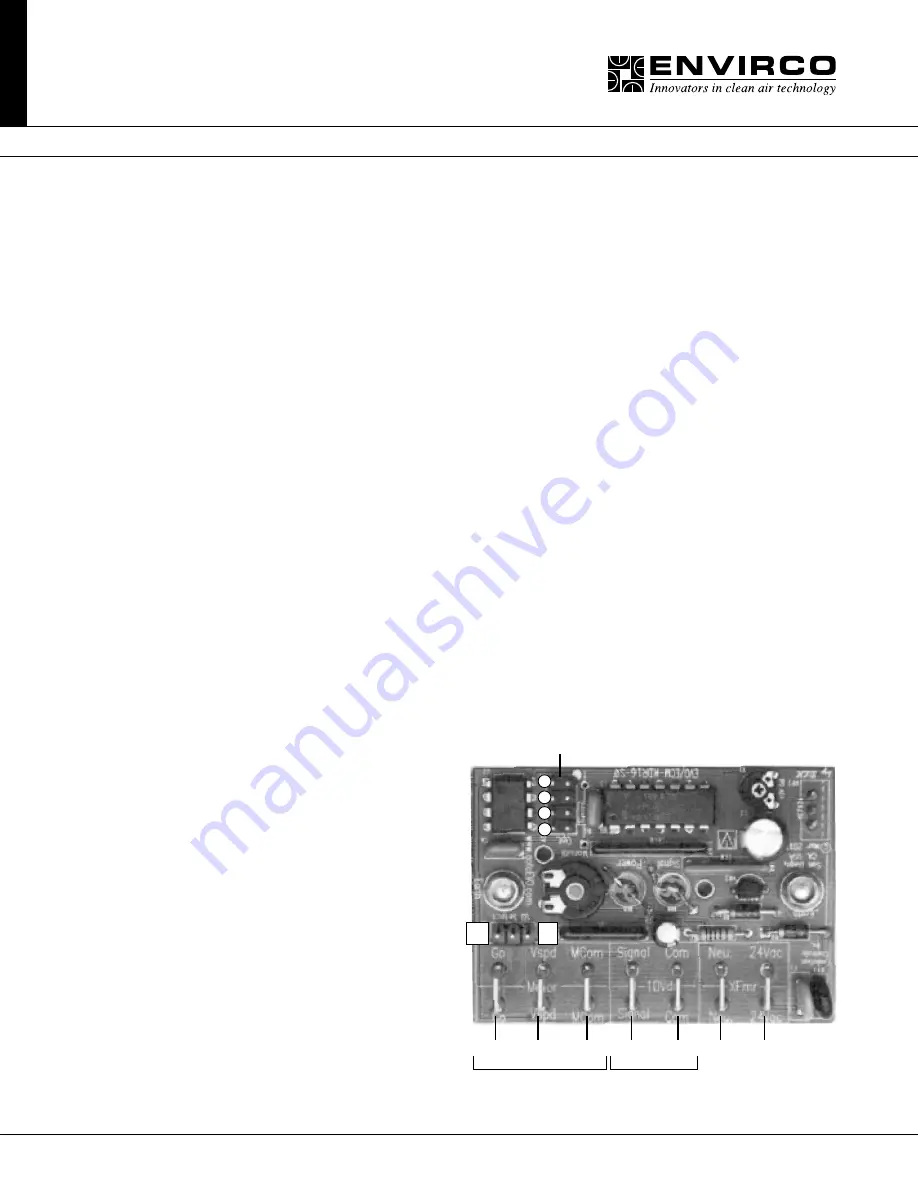
Internal Jumper Options
There are five configurable jumpers inside the MDR16
control box. There is a block of four jumpers:
Jumpers
#1, #2, #3
and
#4
, near the top left corner of the
printed circuit board. Configuration of
Jumpers #1-4
is
accomplished by placing the jumper on or removing the
jumper. These jumpers should not be configured while
the MDR is powered on. A white dot on the printed
circuit board denotes
Jumper #1
.
Jumper #1
, if present, configures the MDR16 to provide
a 10 second spin-up delay for the FFUs, in which the
motor or motors will operate at a minimum speed for
the first 10 seconds after power-up.
Jumper #2
, if present, configures the MDR16 for
automated input control.
Jumper #3
, Manual Override, permanently enables
Lost Signal Override and allows use in manual mode.
Jumper #4
has two functions. It sets the control input
range/mode and enables stopping the FFUs if the
Jumpers 1-4
Jumper 5
Go Vspd Vcom Signal Com Neu. 24Vac
1
2
3
4
ON
ON
ON
OFF
ECM
Control
Automation
Input