


Command Line Interface
4-28
4
IP Filter Commands
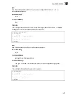
management
This command specifies the client IP addresses that are allowed management
access to the switch through various protocols. Use the
no
form to restore the
default setting.
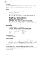
Syntax
[
no
]
management
{
all-client
|
http-client
|
snmp-client
|
telnet-client
}
start-address
[
end-address
]
•
all-client
- Adds IP address(es) to the SNMP, web and Telnet groups.
•
http-client
-
Adds IP address(es) to the web group.
•
snmp-client
-
Adds IP address(es) to the SNMP group.
•
telnet-client
- Adds IP address(es) to the Telnet group.
-
start-address
- A single IP address, or the starting address of a range.
-
end-address
- The end address of a range.
Default Setting
All addresses
Command Mode
Global Configuration
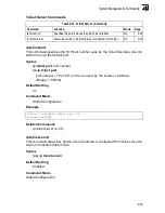
Command Usage
• If anyone tries to access a management interface on the switch from an
invalid address, the switch will reject the connection, enter an event
message in the system log, and send a trap message to the trap manager.
• IP address can be configured for SNMP, web and Telnet access
respectively. Each of these groups can include up to five different sets of
addresses, either individual addresses or address ranges.
• When entering addresses for the same group (i.e., SNMP, web or Telnet),
the switch will not accept overlapping address ranges. When entering
addresses for different groups, the switch will accept overlapping address
ranges.
• You cannot delete an individual address from a specified range. You must
delete the entire range, and reenter the addresses.
• You can delete an address range just by specifying the start address, or by
specifying both the start address and end address.
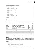
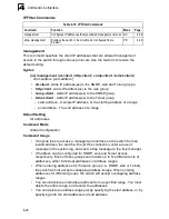
Table 4-10. IP Filter Commands
Command
Function
Mode
Page
management
Configures IP addresses that are allowed management access GC
4-28
show management
Displays the switch to be monitored or configured from a
browser
PE
4-29
Summary of Contents for Matrix-V V2H124-24P
Page 2: ......
Page 8: ...Notice vi...
Page 22: ...Contents xx...
Page 26: ...Tables xxiv...
Page 30: ...Figures xxviii...
Page 38: ...Introduction 1 8 1...
Page 50: ...Initial Configuration 2 12 2...
Page 159: ...Port Configuration 3 109 3 Figure 3 66 Displaying Etherlike and RMON Statistics...
Page 234: ...Configuring the Switch 3 184 3...
Page 480: ...Command Line Interface 4 246 4...
Page 496: ...Index Index 4...
Page 497: ......
Page 498: ...Part 150200039400A FW 2 5 2 0 E012005 R02 ES3526G E072000 R04...


