Setting Up the Matrix N7 Chassis
3-12
Matrix N7 Chassis Setup
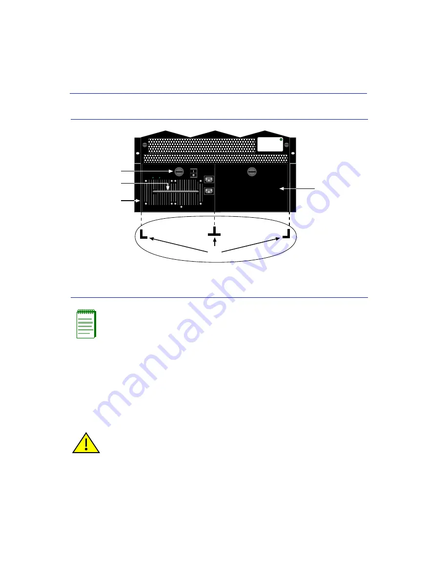
Figure 3-7
Installing the Power Supply Module(s)
After completing the power supply and module installations, the Matrix N7 chassis is ready to be
powered up. Proceed to
Section 3.3
for instructions to power up the chassis.
3.2.5
Removing a Power Supply
To remove a 7C203-1 power supply, refer to
Figure 3-8
and proceed as follows:
1.
Attach the anti-static wrist strap as described in
Section 3.2.3.3
before handling the power
supply module.
2.
Set the power supply
0/|
Power switch
➀
to
0
.
➀
Mandatory power supply installed in slot PS1
➃
Slotted screw
➁
Power supply handle
➄
Blank plate covering slot PS2
➂
Card guides
NOTE:
To install the modules, refer to the module installation guide for the installation
instructions. Before you power up the Matrix N7 chassis, it is recommended that you
complete the installation of the modules in the chassis.
CAUTION:
Always set the
0/|
power switch to
0
before removing a power supply from
the chassis.
50/60Hz
LINE 2:
100-125V~12A
200-240V~6A
50/60Hz
LINE 1:
100-125V~10A
200-240V~5A
POWER
FAN
PS1
À
Ã
Á
Â
Ä
Summary of Contents for Matrix N7 7C107
Page 2: ......
Page 10: ......
Page 18: ...Document Conventions xvi About This Guide...
Page 24: ...Getting Help 1 6 Introduction...
Page 46: ...Removing and Reinstalling the Fan Tray 3 18 Matrix N7 Chassis Setup...


