background image


Page 8 

Copyright Enphase Energy Inc. 2011 

141-00013 Rev 03b


Selecting Cable Type 

Enphase Engage Cable is available in two different voltage types and two 
connector spacing options. Depending upon installer needs, the cable is also 
available in different lengths. 
 
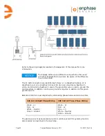
The cable is installed by simply rolling out 
the desired length of cable and cutting it to 
size. One end is wired directly into the 
junction box at the head of the branch 
circuit, eliminating the need for a separate 
AC interconnect cable. The other end is 
sealed from the environment using an 
Enphase Branch Terminator. The 
microinverter AC cable connectors are then 
plugged into the regularly-spaced connectors 
as shown. 
 

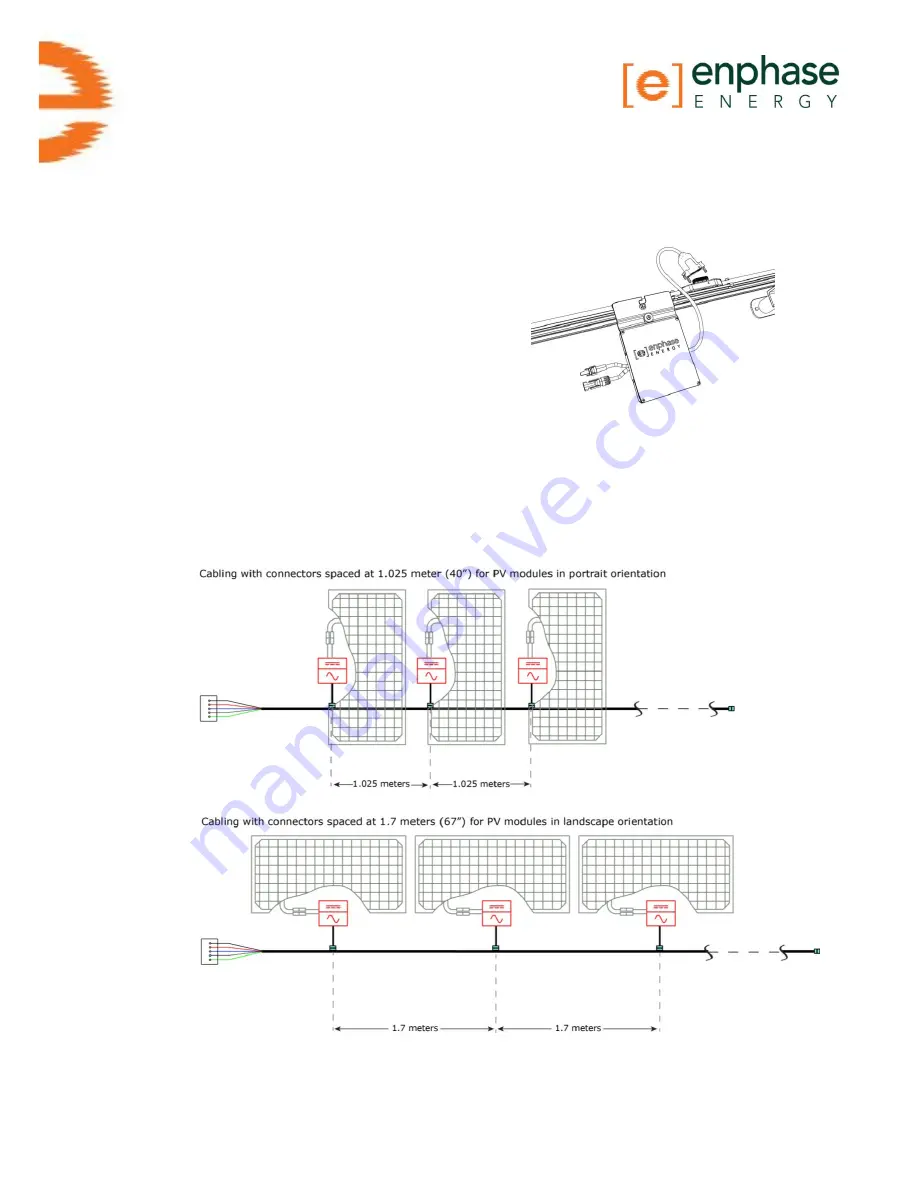
Connector Spacing Options  

The gap between connectors on the cable can be either 1.025 meters (40”) or 1.7 
meters (67”). The 1.025 meter spacing is best suited for connecting PV modules 
installed in portrait orientation, while the 1.7 meter gap is best suited to PV 
modules installed in landscape orientation. 


Summary of Contents for ET10-208-30

Page 1: ...Installation Manual Enphase Engage Cable and Accessories ...

Page 2: ...etaluma CA 94952 Phone 707 763 4784 Toll Free 877 797 4743 Fax 707 763 0784 http www enphase com info enphaseenergy com Other Information Product information is subject to change without notice All trademarks are recognized as the property of their respective owners Copyright 2011 Enphase Energy All rights reserved ...

Page 3: ...gage Cable and Accessories Installation 11 Installation Procedure 12 Step 1 Measure AC at Service Entrance Conductors 12 Step 2 Install the AC Branch Circuit Junction Box 13 Step 3 Position the Enphase Engage Cable 14 Step 4 Attach the Microinverters to the Racking 14 Step 5 Dress the Engage Cable 15 Step 6 Terminate the Unused End of the Engage Cable 17 Attaching the Terminator 17 Replacing or Re...

Page 4: ...Page 4 Copyright Enphase Energy Inc 2011 141 00013 Rev 03b ...

Page 5: ...Shock Do NOT connect or disconnect the photovoltaic module from the Enphase Microinverter without first removing AC power from the photovoltaic system Electrical Installation Be aware that only trained solar professionals should install and or replace the Enphase Cabling System or connect the Enphase Microinverter to the electrical utility grid Perform all electrical installations in accordance wi...

Page 6: ...Page 6 Copyright Enphase Energy Inc 2011 141 00013 Rev 03b ...

Page 7: ... page 8 for options Watertight sealing caps as needed for any unused drops on the cable Terminators as needed for AC branch circuit cable ends Cable clips Enphase disconnect tool number 2 Phillips screwdriver can be substituted Other items Outdoor rated weather proof AC junction box es Grounding conductor Torque wrench sockets wrenches for mounting hardware Adjustable wrench or open ended wrench f...

Page 8: ...he junction box at the head of the branch circuit eliminating the need for a separate AC interconnect cable The other end is sealed from the environment using an Enphase Branch Terminator The microinverter AC cable connectors are then plugged into the regularly spaced connectors as shown Connector Spacing Options The gap between connectors on the cable can be either 1 025 meters 40 or 1 7 meters 6...

Page 9: ...r a list of approved PV module racking types refer to the Racking Compatibility document at http www enphase com support downloads Cabling Length Options Engage Cabling is available in shorter lengths with 30 40 connectors depending upon voltage type Longer lengths can be ordered and cut to suit per order Ordering options include Model Number Voltage type conductor Connector count Connector spacin...

Page 10: ... cut to service each smaller array and the sub arrays are connected together using appropriately rated lengths of conduit The transition from cable to conduit is accomplished using an outdoor rated AC junction box as required by the NEC and local code Unused connectors must be covered with Enphase watertight sealing caps Mixture of PV modules in both portrait and landscape orientation When PV modu...

Page 11: ...b Enphase Engage Cable and Accessories Installation Follow the instructions in this section to install the Engage Cable For information on microinverter installation refer to the M215 Installation and Operation Manual at http www enphase com support downloads ...

Page 12: ...Enphase Microinverters to the utility grid or energize the AC circuit s until you have completed all of the installation procedures as described in the following sections Step 1 Measure AC at Service Entrance Conductors Measure AC line voltage at the service entrance conductors Acceptable ranges are shown in the following table 240 Volt AC Split Phase 208 Volt AC 3 Phase L1 to L2 211 to 264 Vac L1...

Page 13: ... of Engage Cable Typically three wire sections and several wire terminations must be quantified There is also some resistance associated with each OCPD OverCurrent Protective Device typically a circuit breaker As all of these resistances are in series they add together Since the same current is flowing through each resistance the total voltage drop is total current times the total resistance For a...

Page 14: ... allow for the widest PV modules compatible with Enphase Microinverters If narrower modules are used it may be necessary to account for excess cable by adding a loop of cable at suitable intervals Step 4 Attach the Microinverters to the Racking a Mount the microinverters according to the microinverter manual Ensure both that the microinverter does not interfere with the PV module frames or stiffen...

Page 15: ...e are two release holes in the cable connector These holes are used to disconnect the connector Keep these release holes clear and accessible a Attach the Engage Cable to the rack using the included clips or you may use tie wraps The cable clips are designed so that the drop cable from the microinverter can also be dressed into the clip underneath the cable b Dress any excess cabling in loops so t...

Page 16: ...t sealing caps are installed on all unused AC connectors Unused AC connectors are live when the system is energized by the utility Do not use the shipping cap to cover unused connectors The shipping cap does not provide an adequate environmental seal Enphase watertight sealing caps included in the Installation Kit are required for protection against moisture ingress Enphase watertight sealing caps...

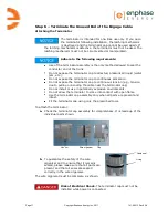
Page 17: ...o continuous immersion Do not expose the terminator cap to continuous tension e g tension due to pulling or bending the cable near the terminator cap Do not install or use in potentially explosive environments Do not allow the terminator to come into contact with open flame Use the terminator cap assembly only when all parts are present and intact Fit the terminator cap using only the prescribed t...

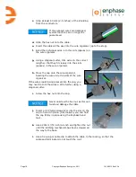
Page 18: ...er h Press the cap onto the wire organizer bending the wires into the slots of the wire organizer If the wires resist being pressed into the cap you may need to trim the wires a little further using a diagonal cutter i Screw the hex nut onto the cap Never unscrew the hex nut as this can twist and damage the cable j Insert a 2 Philips screwdriver into the slot on the cap to hold it in place Alterna...

Page 19: ...roy the latching mechanism meaning that the unit then cannot be used again a Remove the terminator by cutting it off using a diagonal cutter set flush against the end of the cable b Replace the terminator as described in the previous steps beginning on page 17 Step 7 Connect the Engage Cable to Junction Box es Perform the following steps in accordance with NEC regulations a Connect Engage Cable in...

Page 20: ...is sheathed in blue 208 Vac only Neutral is sheathed in white and Ground is sheathed in green The grounding wire is used to ground the microinverters A WEEB or continuous ground is required in addition to this green grounding wire Balanced 208 VAC is accomplished by alternating phases between microinverters 240 Volt AC Split Phase Wiring 208 Volt AC Three Phase Wiring Black L1 Red L2 White Neutral...

Page 21: ... DC wiring is correct a Ensure that none of the AC and DC wires are pinched or damaged b Ensure that all junction boxes are properly closed c Ensure that all unused connectors are capped d Ensure that all connectors are properly seated e Install the microinverters and commission the system as instructed by the Enphase Microinverter installation and operation manual ...

Page 22: ...from the PV array racking 6 The microinverter connectors are tool removable only The installation kit includes a disconnect tool with two prongs To disconnect a microinverter from the cabling system insert these two prongs into the two holes in the cable connector Squeeze the sides of the disconnect tool to engage with the connector Rock the connector back and forth while pulling gently to disenga...

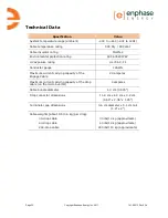
Page 23: ... Conductor gauge 12AWG Maximum current carrying capacity of the Engage Cable 20 amperes Maximum current carrying capacity of the drop cable on the microinverter 4 amperes Cable bundle diameter 1 3 cm 0 525 Drop connector dimensions 11 8 cm x 6 0 cm x 3 2 cm 4 64 x 2 36 x 1 25 Terminator cap dimensions 3 6 cm diameter x 5 1 cm tall 1 4 x 2 Cable weights about 1lb 0 5 kg per drop 30 drop cable 40 dr...

Page 24: ...Page 24 Copyright Enphase Energy Inc 2011 141 00013 Rev 03b ...

Page 25: ...Page 25 Copyright Enphase Energy Inc 2011 141 00013 Rev 03b Appendix Sample Wiring Diagrams Sample Wiring Diagram 240 Vac ...

Page 26: ...Page 26 Copyright Enphase Energy Inc 2011 141 00013 Rev 03b Sample Wiring Diagram 208 Vac ...

Page 27: ......

Page 28: ...Enphase Energy Inc 201 1St Street Petaluma CA 94952 Phone 707 763 4784 TOLL FREE 877 797 4743 Fax 707 763 0784 www enphase com info enphaseenergy com ...

Reviews: