Section 78
- 11 -
00-02-1183
2019-11-21
Configuration Information
Follow these steps to download a custom configuration to the PV500 display:
Step
Action
1
Turn off the display.
2
Insert the USB harness 78000668 into Port A of the display. Then insert a USB
drive that contains the new configuration file into the USB connector on that
harness.
3
Place a magnet into the notch shown here on the upper middle side of the back
of the display:
4
Power the display back on, continually holding the magnet in place.
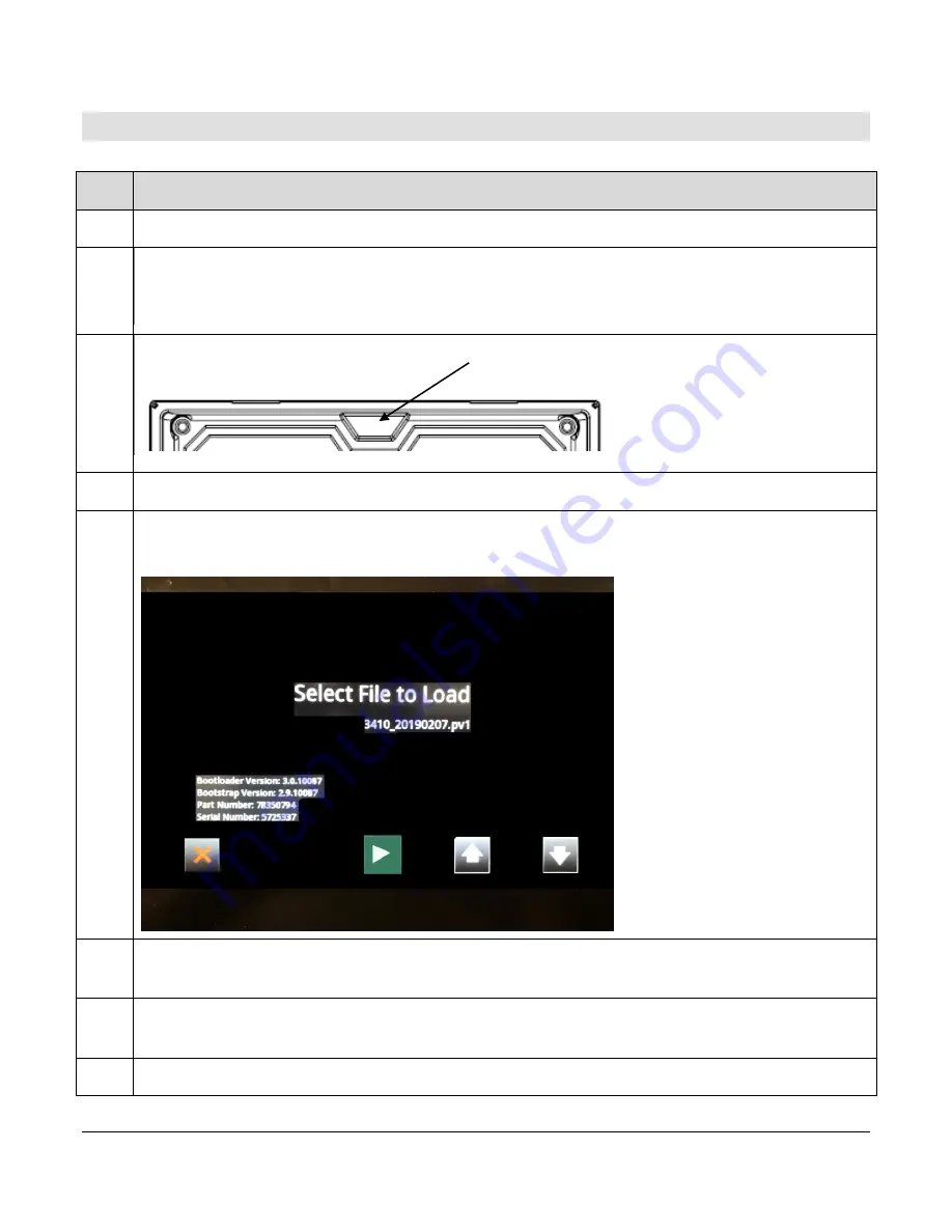
5
Remove the magnet when the display shows the utility for loading new software.
6
Touch the up or down arrow keys on the screen until the appropriate configuration file
from the USB to be loaded into the display is shown on the screen.
7
Press the right arrow/green arrow key on the screen twice to load the selected
configuration.
8
Once completed, the unit will reboot into the loaded application.
Summary of Contents for MURPHY PowerView PV500
Page 1: ...00 02 1183 2019 11 21 Section 78 PowerView ModelPV500 Installation Manual ...
Page 4: ...Section 78 iii 00 02 1183 2019 11 21 THIS PAGE INTENTIONALLY LEFT BLANK ...
Page 5: ......
Page 8: ...Section 78 6 00 02 1183 2019 11 21 ...
Page 10: ...Section 78 8 00 02 1183 2019 11 21 ...
Page 12: ...Section 78 10 00 02 1183 2019 11 21 Pinout Specifications Standard Version ...
Page 16: ...Section 78 14 00 02 1183 2019 11 21 Dimensions Part 78051705 Mounting Bracket ...
Page 17: ...Section 78 15 00 02 1183 2019 11 21 ...
Page 18: ......


