background image

27

ENVOY • MANUAL

Initial Setup


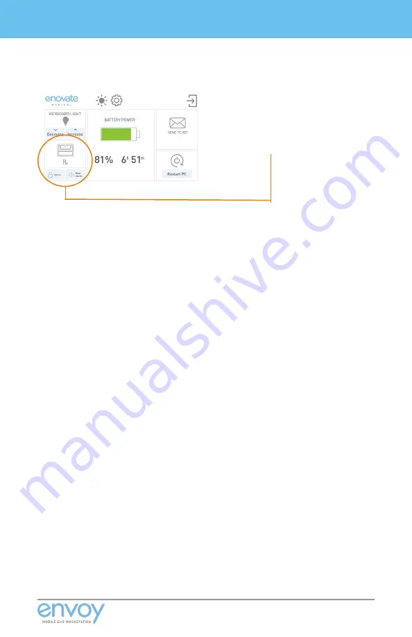
IMPORTANT: If your workstation has medication 
bins, the up/down arrow icons will be replaced 
with a medbin icon.

Home


Screen


Detail


View

 - 

meDbin


unit

USER ID

For complete instructions, please visit our website at www.enovatemedical.com, (Drivers and 
Downloads, Envoy Software User Guides, Touch Screen User Interface)

Summary of Contents for Envoy

Page 1: ...MANUAL 02 07 19 Rev 001 ...

Page 2: ... Warnings 5 Statement of Use 7 Unpacking 11 Cable Management 13 Initial Setup 14 Powering On 22 User Interface 23 Maintenance and Repairs 31 Power Systems 34 Power Systems 35 Power Specifications 43 System Electromagnetic Emissions 47 ...

Page 3: ...N WAS DESIGNED TO SET A NEW STANDARD IN QUALITY ENOVATE MEDICAL S GOAL IS TO PROVIDE A WORKSTATION THAT IS BUILT RIGHT READY FOR YEARS OF USE AND BACKED BY A COMMITMENT OF EXEMPLARY SERVICE AND SUPPORT THANK YOU FOR PURCHASING THE Enovate Medical Envoy Distributed by Enovate Medical 1152 Park Avenue Murfreesboro TN 37129 Support enovatemedical com Toll free 888 909 8906 ...

Page 4: ...l workstation frequently employ the use of symbols with or without accompanying text Health products regulatory agencies require the use of symbols often in place of textual statements to enhance the legibility of labeling and thus improve the conspicuousness of required information such as important safety information Your attention to the presence and content of symbols used in this manual will ...

Page 5: ...PUSHING TO PROHIBIT PUSHING AGAINST AN OBJECT EMERGENCY STOP The term symbols refers to the use of graphical symbols without equivalent accompanying text Symbols are used by medical device manufacturers to create uniform labels and labeling for the UnitedStates European Union and any other countries that may permit their use in medical products The use of symbols on the product labels are intended...

Page 6: ...N unless directed to do so through Enovate Medical approved documentation i e this User Manual or other instructions Only Enovate Medical or an Enovate certified entity may service or replace the Workstation components If any component on the Workstation is missing or damaged the Workstation must not be used Contact Enovate Medical immediately to request service MAINTENANCE During preventive maint...

Page 7: ...ibly cause fire explosion and or death THE CHARGER CONTAINS DANGEROUS VOLTAGES AND THE COVER SHOULD NOT BE REMOVED All service or maintenance work should be carried out by qualified service personnel by contacting Enovate Medical at 888 909 8930 GROUNDING Connect the Enovate workstation or bay charger to an equivalent receptacle marked Hospital Only or Hospital Grade to ensure ground WARNING To av...

Page 8: ...ight can severely damage it The EcoFlex Power and Mobius Power systems have no user serviceable internal parts To maintain your warranty refer all servicing to Enovate Medical qualified personnel Do not cover or obstruct any venting holes on the Envoy workstation with EcoFlex Power or the Mobius Power Charging Stations Store the workstation with EcoFlex Power within 10 to 30 degrees Celsius 50 to ...

Page 9: ...ure Range 20 C to 50 C 4 F to 122 F Atmospheric Pressure 50 kPa to 106 kPa Relative Humidity 5 to 85 non condensing STORAGE REQUIREMENTS The lithium ion Battery Pack must not be fully charged prior to storing 50 state of charge recommended OPERATING ENVIRONMENT Ambient Temperature Range 0 C to 40 C 32 F to 104 F Atmospheric Pressure 50 kPa to 106 kPa Relative Humidity 20 85 non condensing WARRANTY...

Page 10: ...ttery Iron Phosphate Battery IEC 60601 1 3rd Edition UL 1012 CAN CSA E60335 IEC 60335 IEC 62133 2nd Edition UL 62133 Only part numbers 3117615 3117715 3117815 3117915 3118015 3118115 3118215 3118315 3118415 UN 38 3 IEC 62133 UL 1642 UL 2054 UN 38 3 FCC CE COMPLIANCE ...

Page 11: ...ce will not occur in a particular installation If this equipment does cause harmful interference to radio television or Medical Electrical Equipment reception which can be determined by turning the equipment off and on the user is encouraged to try to correct the interference using one or more of the following measures reorient or relocate the receiving antenna increase the separation between the ...

Page 12: ...tations ALL batteries must be fully charged to ensure the duration of their warranty Before removing the Envoy from a shipping container check over the packaging and pallet to prevent accepting an item with shipping damage 1 2 3 Use scissors or a utility knife to cut and remove the two outer straps Remove cardboard lid and cardboard spacers Unpacking ...

Page 13: ...alls and plastic bag NOTE This step requires two people Lift Workstation with foam castor braces still attached out of the cardboard base 4 5 6 Remove foam castor braces Open tray and check for integration kit and locate all optional accessories ...

Page 14: ...hannel 2 Plug in all USB video and audio cables into channel 1 2 3 Mouse and Keyboard Routing Channels 1 2 3 USB A 2 0 1 USB B From PC Computer Only USB A 2 0 USB A 3 0 Computer Monitor Peripheral Monitor Cable Routing Point 1 2 3 MONITOR ARM CABLE ROUTING CLIP MONITOR ARM REAR CABLE ROUTING POINT Cable Management Cable Management Illustration ...

Page 15: ...g 10 lbs Column Drawer 9 1 kg 20 lbs CPU COMPARTMENT Width 406 4mm 16 Depth 330 2mm 13 Height 57 2mm 2 25 I O PORTS Computer Monitor Peripheral USB A 2 0 hub USB A 2 0 hub USB A 3 0 hub USB B from PC 120 VAC 1 0 A 60 Hz Hybrid models only Mouse and Keyboard Routing Channels 1 2 3 USB A 2 0 1 USB B From PC Computer Only USB A 2 0 USB A 3 0 Computer Monitor Peripheral Monitor Cable Routing Point 1 2...

Page 16: ...s with the monitor pole VESA plate and tighten the screws MONITOR AND LAP TOP NUC INSTALLATION STEP 4 Remove cable cover at the monitor base routing point STEP 2 Unlock both sides of the work surface STEP 3 Remove work surface by lifting up Initial Setup ...

Page 17: ...6 Continue routing each cable behind the arm and through the rear cable port at the base of the monitor arm STEP 7 Follow Steps 1 6 for Montitor and Computer Installation STEP 8 Plug Monitor Power Cable pictured in red for demonstration purposes only into channel 2 monitor port and connect the video cable picutred in blue for demonstration purposes only to the computer to your NUC Laptop or Thin C...

Page 18: ...ial Setup All in One Follow steps 5 6 for computer AIO power cable and USB AB Cable All in one Computer power cable should be plugged into Channel 1 USB A B cable should be plugged into USB B USB B ALL IN ONE INSTALLATION ...

Page 19: ...STEP 1 Unlock both sides of the work surface STEP 2 Remove work surface by lifting up STEP 3 Pull the keyboard tray forward to full extension This will simulate the full length requirement of the keyboard cable KEYBOARD INSTALLATION ...

Page 20: ...rface and cable cover at the base of the monitor arm close and lock or continue to next step and install mouse STEP 5 Plug the keyboard cable into the appropriate location on CPU Laptop shown in red For All in Ones shown in blue Option 1 plug into the USB port or Option 2 run to the All in One Computer and plug in ...

Page 21: ... cable length STEP 3 Route the cable under and through the tray STEP 6 Stow mouse in mouse holder STEP 5 Replace the work surface close and lock STEP 4 Plug the mouse cable into the appropriate location on CPU Laptop shown in red For All in One mouse cable shown in blue Option 1 plug into the USB port or Option 2 run to the All in One Computer and plug in MOUSE INSTALLATION STEP 1 Follow steps 1 t...

Page 22: ...beneath the work surface NOTE Take care in computer placement consider orientation based on direction of cable inputs and sizes INCLUDING monitor input power input mouse keyboard and any peripherals Make cable connections within the tray LAPTOP AND MINI FORM FACTOR INTEGRATION STEP 2 Open the CPU compartment by unlocking and removing the work surface locks are located either side of the desk 16 13...

Page 23: ...10 lbs Column Drawer 9 1 kg 20 lbs CPU COMPARTMENT Width 406 4mm 16 Depth 330 2mm 13 Height 57 2mm 2 25 I O PORTS Computer Monitor Peripheral USB A 2 0 hub USB A 2 0 hub USB A 3 0 hub USB B from PC 120 VAC 1 0 A 60 Hz Hybrid models only Mouse and Keyboard Routing Channels 1 2 3 USB A 2 0 1 USB B From PC Computer Only USB A 2 0 USB A 3 0 Computer Monitor Peripheral Monitor Cable Routing Point 1 2 3...

Page 24: ...CT CABLES UNDER THE WORKSURFACE MUST BE CONNECTED PRIOR TO USE AND IF THE WORKSTATION IS BEING PLACED IN LONG TERM STORAGE THE WORKSTATION MUST BE UNPLUGGED PRIOR TO DISCONNECTING THE BATTERY CABLE IMPORTANT Check to ensure that the emergency stop button is not pushed in If it is pull it out to re enable the actuator power The emergency stop button interrupts the up down movement of the workstatio...

Page 25: ...24 Initial Setup ENVOY MANUAL ...

Page 26: ...HERE ARE THREE WAYS TO LOGIN TO THE ENVOY STEP 1 Key FOB Login Ensure your key FOB is powered on and select your name from the list when it appears Please see your IT department for key FOB login details STEP 2 Manual Login Enter your PIN code Please see your IT department for PIN code details STEP 3 Guest Login Sign in as a Guest by selecting Guest from the user list User Interface ...

Page 27: ...est Home Screen Detailed View HEIGHT ADJUSTMENT Adjust the height of the workstation with the up down arrow keys on the touch display or the up down arrows at the base of the monitor arm If the workstation has a medication bins use the up down arrow key on the workstation located directly in front of the monitor pole Submit service request feature only available on workstations connected to RHYTHM...

Page 28: ...cation bins the up down arrow icons will be replaced with a medbin icon home screen detail view medbin unit USER ID For complete instructions please visit our website at www enovatemedical com Drivers and Downloads Envoy Software User Guides Touch Screen User Interface ...

Page 29: ...28 Movement ENVOY MANUAL Release brakes to allow movement Autotrax casters automatically engage Press down on brake to lock casters push brake up to release Movement ...

Page 30: ...29 ENVOY MANUAL Lables Position 1 Position 7 Position 6 Position 5 Position 4 Position 2 3 Position 8 Labels ...

Page 31: ...30 Lables ENVOY MANUAL Position 9 Position 10 Position 11 ...

Page 32: ...31 ENVOY MANUAL Lables 11 2 1 3 9 4 7 5 8 10 5 7 ...

Page 33: ...OFF 2 3 CPU Compartment 4 5 kg 10 lbs 4 Keyboard Tray 1 4 kg 3 lbs 5 Column Mounted Accessories below keyboard tray 4 5 kg 10 lbs 6 Maximum Monitor Weight 7 3 kg 16 lbs telescoping pole 6 Do not push 7 Safe Working Load per Tier 2 3 kg 5 lbs INFORMATION 8 Workstation serial number label Emergency Stop 9 EcoFlex serial number label 10 Lithium battery replacement 11 Download Product Manual Quick Sta...

Page 34: ...nal plastic covering that is designed to resist the effects of harsh chemicals in a health care environment WORKSTATION CLEANING INSTRUCTIONS Nonabrasive cleaners or mild cleaning solutions should be used As a precaution we recommend testing the suitability of a cleaning product by applying to an inconspicuous area minimizing the time of exposure and the amount of cleaning agent used dilute as rec...

Page 35: ...tions or other potentially corrosive liquids or substances Do not immerse the Workstation or Workstation components in liquid or allow liquids to flow into the Workstation Wipe cleaner off surface immediately using a damp cloth Thoroughly dry surface after cleaning Do not use flammable cleaners on Workstation surfaces due to proximity of electrical power and equipment IMPORTANT INFORMATION The prece...

Page 36: ...e there are no exposed unprotected electrical conductors Ensure electrical tape or anything that can cover damage has not been applied to power supply cords and devices NOTE If any of the above items exist immediately tag the item remove from service and notify a supervisor or facilities management In Addition Switch off disconnects and equipment before connecting or disconnecting power supply cor...

Page 37: ...36 Power Systems ENVOY MANUAL Power Systems ...

Page 38: ...ck press and release the white circle on the Battery Pack s fuel gauge display The charge level is indicated in 25 increments by the number of status lights appearing between the E Empty and F Full After 3 seconds the status lights will turn OFF Power Systems Charge Capacity LED 1 LED 2 LED 3 LED 4 0 10 FLASH OFF OFF OFF 11 25 ON OFF OFF OFF 26 50 ON ON OFF OFF 51 75 ON ON ON OFF 76 100 ON ON ON O...

Page 39: ...placed and plugged into an outlet slide a Battery Pack into any open slot making sure the FLASHING GREEN indicator light turns on The charge cycle is complete when the indicator light is illuminated SOLID GREEN FULLY CHARGED Solid Green Light CHARGING Blinking Green Light ERROR Solid or Blinking Yel low Light ...

Page 40: ...discarded or handled There are many ways to properly dispose of batteries most of which depends on the type of battery you have Lithium ion rechargeable batteries are less toxic than many others but it is still recommended that they be recycled The Rechargeable Battery Recycling Corporation RBRC manages a collection and recycling program for rechargeable batteries The RBRC accepts rechargeable nic...

Page 41: ...s for basic safety and essential performance NOTE Batteries supplied by Enovate Medical contain certain requirements for reliable operation and Certificates of Conformity to ensure safety Replacement batteries not provided by or authorized by Enovate Medical may compromise performance and safety WHAT CAUSES A LITHIUM BATTERY TO AGE The main enemies of battery longevity are age the number of charge...

Page 42: ...y to express the actual capacity of a battery over time is called full charge capacity FCC FCC is expressed as a percentage of the initial rated capacity of the battery FCC is influenced by the typical discharge load on the battery and by the usage profile Under normal discharge loads lithium batteries have a lengthy service life With moderate use lithium batteries will deliver years of service Si...

Page 43: ...CARE PRACTICES Recommendations for battery use and storage are covered in the Mobius Power User Guide Additional battery care practices are as follows Store lithium batteries between 20 C and 25 C 68 F and 77 F with 30 to 50 SoC Do not disassemble crush or puncture a battery do not short the external contacts on a battery and do not dispose of a battery in fire or water Do not leave batteries expo...

Page 44: ...te of charge that can be configured Set laptop custom charge threshold to increase lifespan and reduce temperature By setting the custom charge threshold to start at 40 capacity and stop at 50 your device s battery will last longer and not generate as much heat when charging Reduce the brightness of the screen to the minimum readable level Some notebooks use function keys to adjust the brightness ...

Page 45: ...44 Power Systems ENVOY MANUAL ...

Page 46: ...on Chemistry Lithium Iron Phosphate Capacity 26 1 Ah Capacity 45 Ah Voltage 10 8 nominal Voltage 12 8 nominal Energy 281 88 Wh Energy 576 Wh Charge Time 4 hrs Charge Time 3 hrs Measurements 31 cm 12 2 H Measurements U1 18 3 cm 7 2 H x 18 3 x 12 7 cm 5 W x 8 cm 3 14 D cm 7 2 W x 13 0 cm 5 2 D Weight 2 5 kg 5 5 lbs Weight 5 8 kg 12 8 lbs BATTERY SPECIFICATIONS MOBIUS CHARGING STATION SPECIFICATIONS ...

Page 47: ...us Iron Phosphate Input Voltage 10 8 VDC nominal 12 8 VDC nominal Input Voltage Range 9 0 VDC 12 6 VDC 9 6 VDC 14 6 VDC Input Current 14 5 A max 14 5 A max Output Voltage 3 Channels variable 5 VDC 24 VDC 3 Channels variable 5 VDC 24 VDC Output Power 3 Channels 120 W max each 3 Channels 120 W max each Output Power Total 161 W nominal 191 W nominal Output Protection Yes Yes Overload Recovery Yes Yes...

Page 48: ...Shutdown at 10 V Auto reset at 11 5 V High DC Input Voltage Shutdown at 16 5 V Auto reset at 16 5 V Short Circuit Overload Output voltage drops but does not shut down Auto reset on removal Over Temperature Shut down when internal hot spot if 105 C 221 F Auto reset on cooling Reverse Polarity on DC Input Side Automotive Mini Blade Fuse 32 V 15 A Compliance Safety Conforms to ANSI AAMI Stan dard ES6...

Page 49: ...48 Power Systems ENVOY MANUAL ...

Page 50: ...m 10 N ENDC0001 ECOFLEX R7 DC PWR CABLE 609 6 mm 24 N ENDC0001L ECOFLEX R7 DC PWR CABLE 50 IN 1270 mm 50 N ENDC0002 ECOFLEX DC PWR CABLE 2 5 X5 5X9 609 6 mm 24 N ENDC0002L ECOFLEX DC PWR CBL 2 5X5 5X9 50 IN 1270 mm 50 N ENDC0003 ECOFLEX DC PWR CABLE 2 5X5 5X14 609 6 mm 24 N ENDC0003L ECOFLEX DC PWR CBL 2 5X5 5X14 50IN 1270 mm 50 N ENDC0004 ECOFLEX DC PWR CABLE 2 1 X 5 5 609 6 mm 24 N ENDC0004L ECO...

Page 51: ... RF energy only for its internal function Therefore its RF emissions are very low and are not likely to cause any interference in nearby elec tronic equipment Harmonic emissions IEC 61000 3 2 EN610003 2 2014 Class A EcoFlex Power is suitable for use in all establishments other than domestic and those directly connected to the public low voltage power supply network that supplies buildings used for...

Page 52: ...Voltage dips short interruptions and voltage variations on power sup ply input lines IEC 61000 4 11 EN 61000 4 11 2004 5 Ut 95 dip in Ut for 0 5 cycle 0 45 90 135 180 225 270 315 70 Ut 30 dip in Ut for 25 cycles 5 Ut 95 dip in Ut for 5 sec 5 Ut 95 dip in Ut for 1 cycle 40 Ut 60 dip in Ut for 5 cycle 5 Ut 95 dip in Ut for 0 5 cycle 0 45 90 135 180 225 270 315 70 Ut 30 dip in Ut for 25 cycles 5 Ut 9...

Page 53: ...52 Power Systems ENVOY MANUAL ...

Page 54: ...g cables than the recommended separation distance calculated from the equation applicable to the frequency of the transmitter Recommended separa tion distance Conducted RF 3 Vrms outside industrial scientific and medical ISM and amateur radio bands 6 Vrms in ISM and amateur radio bands 6 Vrms 150 kHz to 80 MHz d 1 17 P IEC 61000 4 6 EN 61000 1 6 2014 150 kHz to 80 MHz Radiated RF 10 V m 10 V m d 1...

Page 55: ...eclaration electromagnetic immunity EcoFlex Power is intended for use in the electromagnetic environment specified below The cus tomer or the user of EcoFlex Power should assure that it is used in such an environmen TABLE 204 CONTINUED GUIDANCE AND MANUFACTURER S DECLARATION ELECTROMAGNETIC IMMUNITY FOR EQUIPMENT AND SYSTEMS THAT ARE NOT LIFE SUPPORTING NOTE 1 At 80 MHz and 800 MHz the higher freq...

Page 56: ...um output power of the communications equipment Rated maximum output power of transmitter W Separation distance according to frequency of transmitter m 150 kHz to 80 MHz d 1 17 P 80 MHz to 800 MHz d 1 17 P 800 MHz to 2 5 GHz d 2 33 P 0 01 0 12 0 12 0 23 0 1 0 37 0 37 0 75 1 1 17 1 17 2 33 10 3 70 3 70 7 36 100 11 70 11 70 23 30 For transmitters rated at a maximum output power not listed above the ...

Page 57: ...56 Glossary ENVOY MANUAL ...

Reviews: