USER MANUAL
STM 550 / EMSI
–
ENOCEAN MULTISENSOR FOR IOT APPLICATIONS
© 2020 EnOcean | www.enocean.com F-710-017, V1.0
STM 550 / EMSI User Manual | v1.3 | September 2020 | Page 19/97
2.3.6
Acceleration-controlled reporting interval
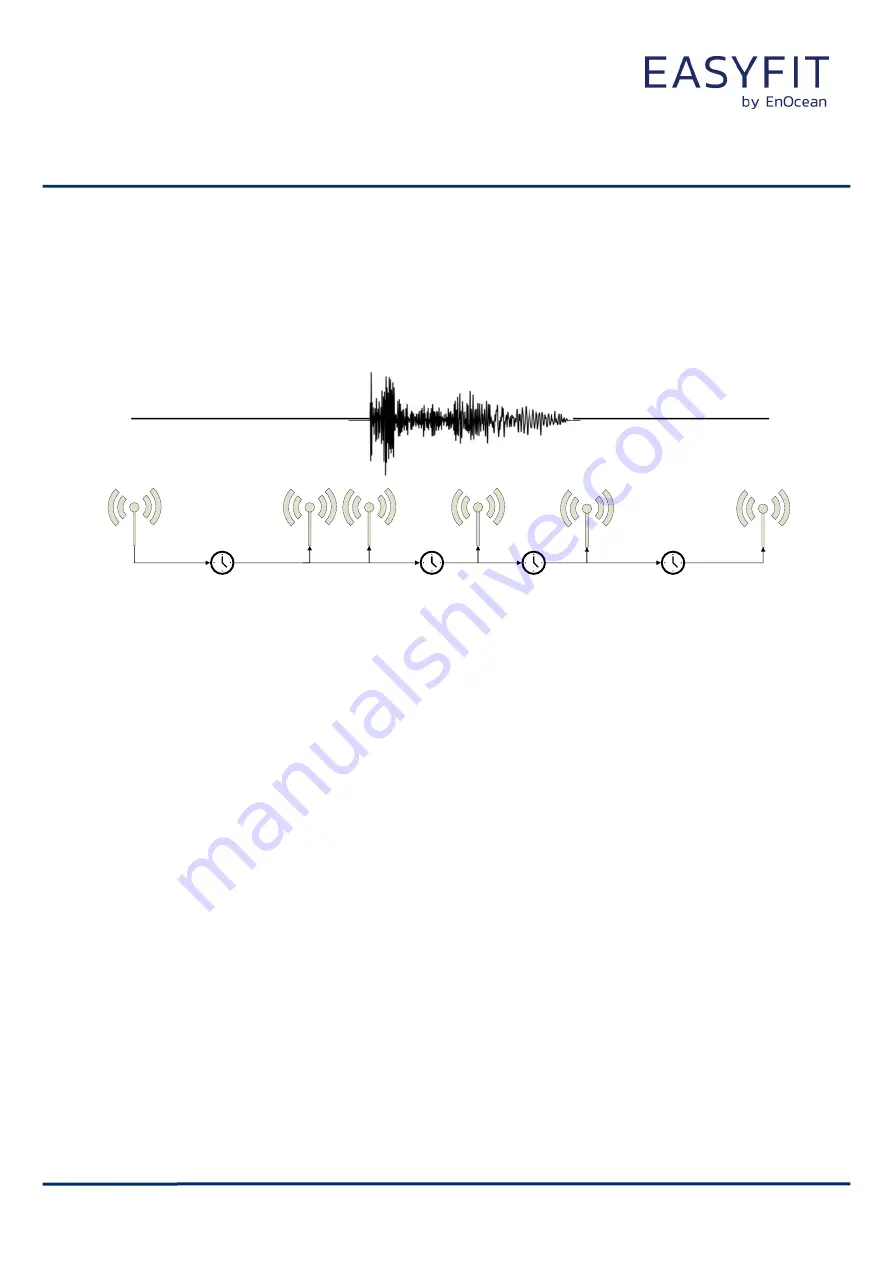
If an asset is in operation or it is being moved, then it might be desirable to receive status
updates more often to determine its status or location.
Figure 6 below illustrates the use of the acceleration-controlled reporting interval.
STANDARD_TX_INTERVAL
ACCELERATION_TX_INTERVAL
STANDARD_TX_INTERVAL
Immediately
ACCELERATION_TX_INTERVAL
Figure 6
–
Acceleration-controlled reporting interval
STM 550 can use acceleration events detected by the acceleration sensor to trigger a higher
update rate. To enable this feature, use the following steps:
1.
Make sure that the EEP selected using the EEP register as described in chapter 9.5.8
reports acceleration
2.
Configure the acceleration sensor parameters (full scale value and sampling fre-
quency) and enable the wake-on-acceleration feature using the ACC_SENSOR_CFG
register described in chapter 9.5.16
3.
Configure the desired acceleration threshold using the ACCELERATION_THRESHOLD
register described in chapter 9.5.21
4.
Configure the desired reporting interval using the ACCELERATION_TX_INTERVAL
register described in chapter 9.5.22
5.
Enable the use of the defined parameters using the ACCELERATION SENSOR bit field
in the THRESHOLD_CFG2 register of the NFC interface as defined in chapter 9.5.14.
Consider the available energy before lowering the reporting interval as discussed in chapter
2.3.1.


