


AM-5175
ENMET Corporation
6
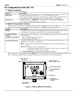
3.3 Relay Contacts
Relay contacts are available for each alarm; these are
SPDT
, rated at 10Amp at 110
V
AC
, and may be latching or non-latching
as required by the application.
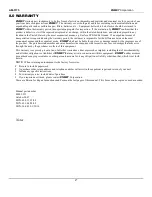
They are accessed on the terminals next to each relay see Figure 5. The contact positions are noted on the circuit board next to
each terminal.
The following table is for the relays in their un-energized state. This is also the alarm condition state. Non-failsafe configured
relays in the alarm state, are the reverse of the PC board labeling. Note that the Fault(FLT) relay cannot be set to operate in a
Non-Failsafe mode. Please see Table 1 below:
Table 1 : Relay Failsafe Settings
Alarm
Position
Alarm 1
J14 (K1)Relay 1 - NO
Normally Open
J14 (K1)Relay 1 - NC
Normally Closed
J14 (K1)Relay 1 - COM
Common
Alarm 2
J15 (K2)Relay 2 - NO
Normally Open
J15 (K2)Relay 2 - NC
Normally Closed
J15 (K2)Relay 2 - COM
Common
Alarm 3
J16 (K3)Relay 3 - NO
Normally Open
J16 (K3)Relay 3 - NC
Normally Closed
J16 (K3)Relay 3 - COM
Common
Fault Alarm
J17 (K4)Relay 4 - NO
Normally Open
J17 (K4)Relay 4 - NC
Normally Closed
J17 (K4)Relay 4 - COM
Common
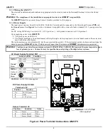
These relay contacts can be used to operate auxiliary alarms or other functions. The relay contacts are DRY, power must be
supplied. It is recommended that power for auxiliary equipment be supplied from an independent power source separate form
the
AM-5175
. Use the existing hole in the enclosure for wire to enter and exit and use appropriate cable fittings. Wiring
should be grouped together,
V
AC
wires should be separated for
V
DC
wires.
Figure 5: Relay Terminal Connections AM-5175
Relays
K1, K2, K3, K4
Relay Terminals
J14, J15, J16, J17
Sensor Terminal J8