ENMET AM-5175 Manual Download Page 4

AM-5175


ENMET Corporation 

2 


2.0 Components of the 

AM-5175 

2.1 AM-5175 elements 

See Figure 1 for location of elements: 

Feature 

Description 

Enclosure 

A polycarbonate box, approximately 7 x 5 x 3, with a detachable front cover. 

4 holes for mounting the enclosure to a vertical surface.  Located at the corners of the bottom 
of the enclosure, directly beneath the 4 front cover retaining screws.  See Figure 3 

Front Cover 

Detachable front cover of 

AM-5175

 with Display Panel.  See Section 2.2 and Figure 1 

There are 4 Screws that hold the front cover in place. 

2.2 AM-5175 Operational Features 

The Display Panel is attached by a cable and is released by unscrewing the 4 screws located in the corners.  After releasing the 
panel, it is swung upward, exposing the interior of the enclosure.  See Figure 1 for location of features. 

Feature 

Description 

Display 

A single line, 8 character LCD with backlight.  Indicates the level of gas detected by sensor. 
The numerical value of gas concentration and other information is displayed. 

Audio Alarm(Horn) 

Audio alarm (105 dB at 30cm/12in).  The audio alarm is activated when the unit is in alarm. 

Visual: 
Indicators and Alarms 

LED indicators: 

Power / Fault Indicator LED, Green / Red 
Alarm (3) Indicator LED, Red 

Membrane Switches 

2 Pushbutton Switches on front panel

 control the instrument maintenance functions.  The 

pushbutton switch locations are indicated by: 

M

ENU


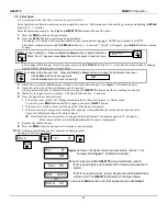
: Advances the instrument display through operation information and maintenance 

menus 

S

ELECT

: Disables audio alarm temporally and  

Selects the maintenance menu operations such as, Zero, Span, Exit menu or sets 
proper calibration values for Zero or Span 

See Section 4.0 and 5.0 for operational and maintenance flow charts. 

Three alarm points are preprogrammed into the 

AM-5175

.  At each alarm point, an LED on the front panel is activated.  There 

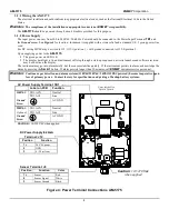
are 4, 10 Amp relay contacts at each alarm point, plus a fault relay.  See Section 3.2 for wiring information. 


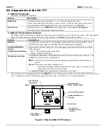
Figure 1: External AM-5175 Features 

Menu

Select

Audio Alarm 

Power Wiring 

Strain Relief 

Visual Indicators: 
Alarm1, Alarm2, Alarm3 

Pushbutton/Membrane 
Switches 

Visual Indicator 

Power/Fault 

Front Cover 
Retaining Screws  
4 places 

Remote Wiring Access 

Sensor 

Summary of Contents for AM-5175

Page 1: ...ENMET Corporation PO Box 979 Ann Arbor MI 48106 0979 www enmet com Manual part number 80003 551 MCN 14 003 03 20 14 AM 5175 Ambient Air Monitor Manual...

Page 2: ...Sensor Replacement 15 5 3 1 A Factory calibration must be performed 15 6 0 Accessory and Replacement Parts 16 7 0 Technical Data and Specifications 16 8 0 WARRANTY 17 List of Tables Table 1 Relay Fai...

Page 3: ...tems packing material and carton As Is Within 5 days of receipt notify the carrier s local office and request immediate inspection of the carton and the contents After the inspection and after you hav...

Page 4: ...information is displayed Audio Alarm Horn Audio alarm 105 dB at 30cm 12in The audio alarm is activated when the unit is in alarm Visual Indicators and Alarms LED indicators Power Fault Indicator LED G...

Page 5: ...14 J15 J16 J17 This group of terminals is located on the Circuit Board For the contacts for each of three alarm relays and for the contacts of a fault relay See Section 3 3 Terminal J12 For VDC back u...

Page 6: ...riate vertical surface leaving room for lid to be opened using the mounting holes provided Avoid areas with excessive vibration or temperature extremes The holes in the bottom of the enclosure are 0 1...

Page 7: ...through a start up sequence unit serial number and software revision may be shown on the display The instrument may go into alarm briefly but the sensors stabilize quickly If the instrument persists i...

Page 8: ...ly Open J14 K1 Relay 1 NC Normally Closed J14 K1 Relay 1 COM Common Alarm 2 J15 K2 Relay 2 NO Normally Open J15 K2 Relay 2 NC Normally Closed J15 K2 Relay 2 COM Common Alarm 3 J16 K3 Relay 3 NO Normal...

Page 9: ...tatus See the Section 4 1 1 below 4 1 1 Typical Start Up When power is supplied to the AM 5175 the instrument will display the following sequence of information Typical start up sequence of informatio...

Page 10: ...Display indicates mA Span range Full Scale Press MENU button Display returns to gas measurent Operational Display Flow Chart 4 2 1 Alarm Conditions AM 5175 There are three alarm set points available T...

Page 11: ...AM 5175 Maintenance Menus Sequence Example of Display Function Normal Display Mode Measurement of CO Press and hold the MENU button for 2 4 seconds to enter the Maintenance Menu The Power Fault LED wi...

Page 12: ...ess the Menu button to cycle through Maintenance Menus Select OR Zero Cal OK If the Zero signal is not within Preset Specs the AM 5175 will display Bad ZERO Menu Bad ZERO If the Zero signal is within...

Page 13: ...is recommended that the Zero procedure be done prior to the Span procedure ENMET Corporation recommends at least quarterly calibration of the AM 5175 instrument Calibration equipment is available fro...

Page 14: ...in 1 2 seconds display will change to Span If you wish to Span the sensor press the SELECT button you are now ready to apply gas Proceed to gas span step 2 If you wish to Exit the maintenance menu pre...

Page 15: ...To exit cal press MENU button until Exit appears and press SELECT button If the sensor is outside of acceptable parameters Bad Span is displayed If the sensor did not respond an incompatible span gas...

Page 16: ...intenance menu as shown in Figure 6 AM 5175 Maintenance Menu flow chart 1 Press the MENU button until to display Span is displayed 2 Press the SELECT button to initiate the mA Span menu 3 Press the ME...

Page 17: ...is present remove the clip before plugging in the new sensor 6 Replace the Sensor PC board and 2 retaining screws 7 Reconnect the instrument to power 8 Recalibrate the instrument See Section 5 2 Step...

Page 18: ...num Cylinders 67028 0200 Sensor H2S 67028 1100 Sensor O2 67028 1200 Sensor CO 73083 000 Carry Case 7 0 Technical Data and Specifications Electrical Power 15 Amp fused branch circuit 100 240 VAC 0 45A...

Page 19: ...sed by the improper use of the product The purchaser indemnifies and saves harmless the company with respect to any loss or damages that may arise through the use by the purchaser or others of this eq...

Page 20: ...processing delays ENMET charges a one hour minimum billing for all approved repairs with additional time billed to the closest tenth of an hour All instruments sent to ENMET are subject to a minimum...

Page 21: ...nt Terms K COD Check one K VISA MasterCard______________________ ________ ________ Card number Expiration Card Code K American Express______________________ ________ ________ Card number Expiration Ca...

Reviews: