background image

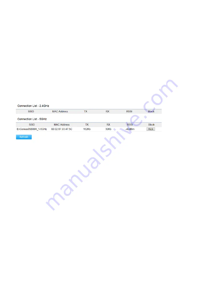
Connections 

Clicking the 

Connections

 link under the 

Device Status

 menu displays the list of clients associated to the Access Point’s 

2.4GHz/5GHz, along with the MAC address, TX, RX and signal strength for each client. Clicking 

Kick

 in the Block column removes 

this client. 


Click 

Refresh

 to refresh the Connection List page. 


Summary of Contents for EWS660AP

Page 1: ......

Page 2: ...10 Physical Interface 12 Chapter 2 13 Considerations for Wireless Installation 14 Computer Settings 15 Hardware Installation 19 Mounting the Access Point 20 Chapter 3 22 Default Settings 23 Web Config...

Page 3: ...ettings 49 Chapter 7 50 SNMP Settings 51 CLI SSH Settings 53 HTTPS Settings 54 Email Alert 55 Date and Time Settings 56 WiFi Scheduler 57 Tools 59 Device Discovery 62 Chapter 8 63 Account Setting 64 F...

Page 4: ...Appendix C CE Interference Statement 74...

Page 5: ...Chapter 1 Product Overview...

Page 6: ...the same time provides 5 GHz band under 802 11ac a n mode for communicating to and from 5 GHz capable computers tablets or smart phones or for transferring files Several EWS660APs can be deployed in a...

Page 7: ...0 Mbps on 5 GHz band Built in high gain antennas for low profile design Backwards compatible with IEEE802 11a b g n wireless devices Integrated Power over Ethernet IEEE802 3at for lowering deployment...

Page 8: ...S XP Vista 7 8 Mac OS or Linux based operating systems Web Browsing Application i e Internet Explorer Firefox Chrome Safari or another similar browser application Package Contents The package contains...

Page 9: ...riums amphitheaters classrooms ballrooms arenas exhibition centers or temporary offices where one wants either a permanent or temporary Wireless LAN established The Ability to Access Real Time Informa...

Page 10: ...Radio BSSID SNMP V1 V2c V3 MIB I II Private MIB VLAN Tag VLAN Pass through Clients Statistics Save Configuration as User Default Fast Roaming E Mail Alert RADIUS Accounting Guest Network Control CLI...

Page 11: ...Physical Environment Conditions Operating Temperature 4 F 131 F 20 C 55 C Humidity non condensing 90 or less Storage Temperature 22 F 176 F 30 C 80 C Humidity non condensing 90 or less...

Page 12: ...Physical Interface Dimensions and Weights Length 304mm Width 181mm Depth 46mm Weight 865g Interface 1 LED Indicators 2 LAN2 3 LAN1 PoE IN 4 Reset Button...

Page 13: ...Chapter 2 Before You Begin...

Page 14: ...e Access Point to have an optimal wireless range during setup Keep the number of walls and or ceilings between the Access Point and other network devices to a minimum Each wall and or ceiling can redu...

Page 15: ...7 In order to use the Access Point you must first configure the TCP IPv4 connection of your Windows OS computer system 1 Click the Start button and open the Control Panel Windows XP Windows 7 2a In Wi...

Page 16: ...twork status and tasks in the Network and Internet section then select Change adapter settings 3 Right click on Local Area Connection and select Properties 4 Select Internet Protocol Version 4 TCP IPv...

Page 17: ...is different from the Access Point and Subnet mask then click OK Note Ensure that the IP address and Subnet mask are on the same subnet as the device For example Access Point IP address 192 168 1 1 PC...

Page 18: ...ighlight Ethernet 4 In Configure IPv4 select Manually 5 Enter an IP address that is different from the Access Point and Subnet mask then click OK Note Ensure that the IP address and Subnet mask are on...

Page 19: ...to the Ethernet port on the computer 4 Once both connections are secure verify the following a Ensure that the POWER light is on it will be green b Ensure that the 2 4 GHz 5 GHz WLAN light is on it w...

Page 20: ...sticker to the desired location on the wall and use a 6mm drill bit to drill the two marked holes 2 Insert the screw anchors into the 6mm holes drilled then insert and the screws and tighten 3 Align t...

Page 21: ...mounting kit 1 Use a flathead screwdriver to unfasten the screw on the pole mounting ring and thread it through the middle tab on the rear of the access point 2 Mount the access point onto the pole b...

Page 22: ...Chapter 3 Configuring Your Access Point...

Page 23: ...will show you how to configure the device using the web based configuration interface Default Settings Please use your Ethernet port or wireless network adapter to connect the Access Point IP Address...

Page 24: ...http 192 168 1 1 Note If you have changed the default LAN IP Address of the Access Point ensure you enter the correct IP Address 2 The default username and password are admin Once you have entered th...

Page 25: ...3 If successful you will be logged in and see the Access Point User Interface Model name varies depending on model...

Page 26: ...Chapter 4 Overview...

Page 27: ...ns describe these options Device Status Clicking the Device Status link under the Overview menu shows the status information about the current operating mode The Device Information section shows gener...

Page 28: ...CP Client and STP status The Wirelesss LAN Information 2 4 GHz 5GHz section shows wireless information such as Operating Mode Frequency and Channel Since the Access Point supports multiple SSIDs infor...

Page 29: ......

Page 30: ...Status menu displays the list of clients associated to the Access Point s 2 4GHz 5GHz along with the MAC address TX RX and signal strength for each client Clicking Kick in the Block column removes thi...

Page 31: ...Chapter 5 Network...

Page 32: ...her the device IP address will use the static IP address specified in the IP Address field or be obtained automatically when the device connects to a DHCP server IP Address The IP Address of this devi...

Page 33: ...IP Address The IPv6 IP Address of this device Subnet Prefix Length The IPv6 Subnet Prefix Length of this device Gateway The IPv6 Default Gateway of this device Leave it blank if you are unsure of thi...

Page 34: ...nother bridge in the spanning tree does not send a hello packet for a long period of time it is assumed to be inactive Forward Delay Specifies Bridge Forward Delay in seconds Forwarding Delay Time is...

Page 35: ...Chapter 6 2 4GHz 5GHz Wireless...

Page 36: ...to other devices Band Steering Enable Band Steering to sends 802 11n clients to the 5GHz band where 802 11b g clients cannot go and leaves the 802 11b g clients in 2 4GHz to operate at their slower ra...

Page 37: ...reater bandwidth This option is only available when Wireless Mode is 802 11n and Channel HT Mode is 20 40 MHz or 40MHz Channel Select the appropriate channel Transmit Power Select the transmit power f...

Page 38: ...ption reduces the number of packets but also increases packet sizes AP Detection AP Detection can select the best channel to use by scanning nearby areas for Access Points Distance Specifies the dista...

Page 39: ...2 4GHz 5GHz SSID Profile Under Wireless Settings you can edit the SSID profile to fit your needs Click Edit under the SSID you would like to make changes to...

Page 40: ...e the security mode For more details see the next section Hidden SSID Check this option to hide the SSID from clients If checked the SSID will not appear in the site survey Client Isolation Check this...

Page 41: ...h Type Select Open System or Shared Key Input Type ASCII Regular Text Recommended or HEX Hexadecimal Numbers For advanced users Key Length Select the desired option and ensure the wireless clients use...

Page 42: ...he same settings Passphrase Wireless clients must use the same Key to associate the device If using ASCII format the Key must be from 8 to 63 characters in length If using HEX format the Key must be 6...

Page 43: ...he Radius server Radius Accounting Enables or disables the accounting feature Radius Accounting Server Enter the IP address of the Radius accounting server Radius Accounting Port Enter the port number...

Page 44: ...cess Point The default setting is Disable Wireless MAC Filter ACL Access Control List Mode Determines whether network access is granted or denied to clients whose MAC addresses appear in the MAC addre...

Page 45: ...improved Quality of Service Enable Traffic Shaping Select to Enable or Disable Wireless Traffic Shaping Download Limit Specifies the wireless transmission speed used for downloading Upload Limit Spec...

Page 46: ...broadcasting SSID Specify the SSID for the current profile This is the name visible on the network to wireless clients Security You can use None or WPA PSK WPA2 PSK security for this guest network Hi...

Page 47: ...ask IP Address for the Guest Network Automatic DHCP Server Settings Starting IP Address Specify the starting IP Address range for the Guest Network Ending IP Address Specify the ending IP Address rang...

Page 48: ...ient and let it find another AP to handover and associate upon detecting the wireless client s RSSI value lower than specified The RSSI value can be adjusted to allow more clients to stay associated t...

Page 49: ...be physically located next to one another on the LAN Status If your network includes VLANs and if tagged packets need to pass through the Access Point select Enable and enter the VLAN ID Otherwise cli...

Page 50: ...Chapter 7 Management...

Page 51: ...ached devices SNMP allows messages called protocol data units to be sent to various parts of the network Upon receiving these messages SNMP compatible devices called agents returns the data stored in...

Page 52: ...ddress of the computer that will receive the SNMP traps Trap Destination Community Name Specifies the password for the SNMP trap community SNMPv3 Status Enables or Disables the SNMPv3 feature User Nam...

Page 53: ...command console modem or Telnet connection For security s concern you can enable SSH Secure Shell to establish a secure data communication CLI Status Select Enable or Disable to enable or disable the...

Page 54: ...and of itself rather it is the result of simply layering the Hypertext Transfer Protocol HTTP on top of the SSL TLS protocol thus adding the security capabilities of SSL TLS to standard HTTP communica...

Page 55: ...ect to show as the subject of the email Email Account Username Password Enter the username and password required to connect to the SMTP server SMTP Server Port Enter the IP address domain name and por...

Page 56: ...Access Point s internal clock with the computer s time Automatically Get Date and Time Enter the IP address of an NTP server or use the default NTP server to have the internal clock set automatically...

Page 57: ...ing acquired from a network time protocol NTP server For details on how to connect the Access Point to an NTP server see Date and Time Settings Auto Reboot Settings You can specify how often you would...

Page 58: ...z to use WiFi Schedule SSID Selection Select a SSID to use WiFi Schedule Schedule Templates There are 3 templates available Always available Available 8 5 daily and Available 8 5 daily except weekends...

Page 59: ...table to a target in the network Ping Test Parameters Target IP Domain Name Enter the IP address or Domain name you would like to search Ping Packet Size Enter the packet size of each ping Number of...

Page 60: ...Traceroute Parameters Target IP Domain Name Enter an IP address or domain name you wish to trace Start Click Start to begin the trace route operation Stop Halts the traceroute test...

Page 61: ...domain name you wish to run a Speed Test for Time Period Enter the time in seconds that you would like the test to run for and in how many intervals Start Starts the Speed Test IPv4 IPv6 Port The Acce...

Page 62: ...Device Discovery Under Device Discovery you can choose for the Access Point to automatically scan for local devices to connect to Click Scan to begin the process...

Page 63: ...Chapter 8 System Manager...

Page 64: ...ername for logging in to the Administrator Username entry box Current Password Enter the old password for logging in to the Current Password entry box New Password Enter the new password for logging i...

Page 65: ...File System to the location of the Firmware upgrade file 2 Select the upgrade file The name of the file will appear in the Upgrade File field 3 Click the Upload button to commence the Firmware upgrade...

Page 66: ...the original default settings To Configure the Backup Restore Settings click Firmware under the Systems Manager tab Factory Setting Backup Setting Click Export to save the current device configuratio...

Page 67: ...the System Log page Status Enables or disables the System Log function Log Type Select the Log Type mode you would like to use Remote Log Enables or disables the Remote Log feature If enabled enter th...

Page 68: ...Reset In some circumstances you may be required to force the device to reboot Click on Reset and you will have the choice to reboot the device or reset the device...

Page 69: ...Logout Click Logout and a warning window will appear Click OK to logout...

Page 70: ...Appendix...

Page 71: ...Appendix A FCC Interference Statement Federal Communication Commission Interference Statement FCC Caution IMPORTANT NOTE Radiation Exposure Statement...

Page 72: ...Appendix B IC Interference Statement Industry Canada Statement Caution Avertissement...

Page 73: ...Radiation Exposure Statement D claration d exposition aux radiations...

Page 74: ...Appendix C CE Interference Statement Europe EU Declaration of Conformity...

Page 75: ...0560...

Page 76: ......

Reviews: