Engbo XF 130 VR Installation And User Manual Download Page 8

XF  

Rev: 4, 2010-02-01 

Page 8 


2.2.6. 

Battery replacement 

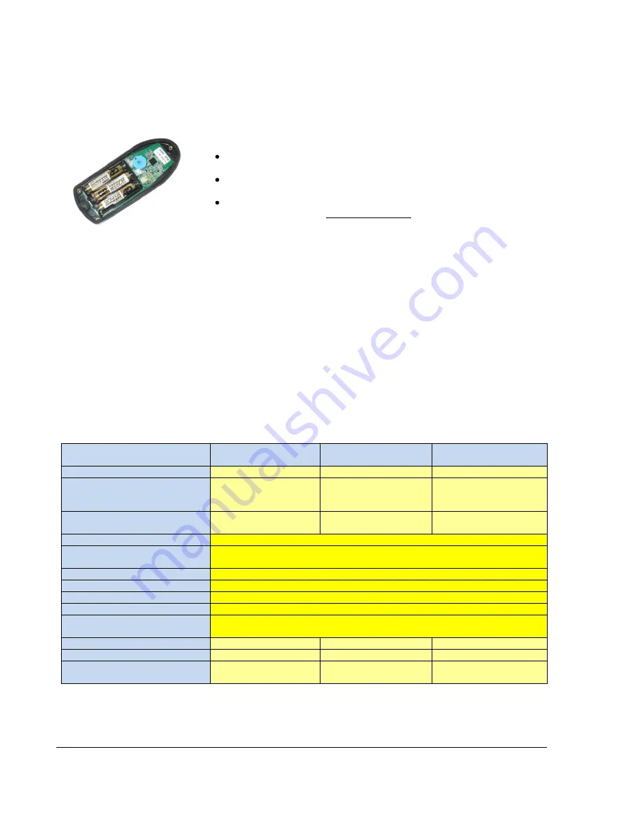
The remote control uses three regular AAA/LR03 alkaline batteries. The battery 
life is more than two seasons under normal leisure use.  
When replacing batteries, open the unit by unscrewing all five screws.  
 

NB:


The screws are of different lengths and have O-rings under the screw 
heads.  


Replace the batteries and make sure all 3 batteries have the 

(

+

and the 

(

–)

 correct. 


Reassemble the back cover and carefully screw the parts together until 
the housing gasket is slightly compressed. The remote will remain 
splashproof as long as the O-rings and gasket are intact with correct 
compression.  


NB:

 To ensure a long lifetime, this remote control has acid-proof machine 

screws and screw inserts in the housing.  


3. Spesifications  

3.1. 

Technical specifications wireless remote control 


Wireless remote: 


Motor Control Unit:


Remote Control Unit:


Model:                          

RC-01 

ECU-01 

RCU 

Power supply:               

3 x 1.5 V DC 

(3 x AAA/LR03 

batteries) 

From thruster 

(integrated) 


From thruster 

(integrated) 


Battery life:        

2

–3 years  

(normal leisure use) 

Not applicable 

Not applicable 

Communication:                        

Two-way, narrowband, GFSK modulation 

Operating frequency:           

868.075 

– 869.125 MHz, CE (EU/EFTA)* 

902.175 

– 903.025 MHz, FCC (US/Canada)* 

Channels:                              

16 for communication 

Channel separation:             

50 kHz 

Address range:           

65.535 (16 bit), spread among the 16 channels 

Temperature range:             

-20 to +60 degrees Celsius/-4 to +131 degrees Fahrenheit 

Relative humidity  
(without condensation): 

20% 

– 90% 

Weight:                       

105 g 

Model dependent 

120 

Dimensions (HxWxD):   

129x53x23 mm 

Model dependent 

150x200x40mm 

Environment protection:  

Splashproof 

IP 41 


IP41 

  * May apply to other countries. For information, please contact local authorities for the country concerned. 
** Conditional upon correct installation and intact rubber gasket and O-rings 

Summary of Contents for XF 130 VR

Page 1: ...v 4 2010 02 01 Page 1 XForce thruster VR series Installation and user manual XF 30 VR XF 60 VR XF 90 VR XF 130 VR English version According to NS EN ISO 9001 2000 FCC ID R78 RC 01 R78 ECU 01 Art no 117 00166 ...

Page 2: ...ng the tunnel 13 4 1 9 Filler 13 4 1 10 Grinding 14 4 1 11 Directions for installations in high speed boats 14 4 1 12 Coating 14 5 THRUSTER INSTALLATION 15 5 1 The thrusters unit 15 5 2 Preparations 15 5 3 Not vertical installation 15 5 4 Off centre installation 16 5 5 Drilling thruster installation holes 16 5 6 Apply sealant 16 5 6 1 Specified sealants 16 5 7 Installation of the gearhousing 16 5 ...

Page 3: ... are based on the same modules which makes it possible to manoeuvre and anchor using one single wireless remote control To achieve maximum benefit from your XForce thruster please study this manual thoroughly before installing and making use of the thruster panels Keep this manual onboard Do not hesitate to contact us if you have any questions Best regards Engbo AS P O Box 2288 Postterminalen N 31...

Page 4: ...ow voltage The system has intelligent monitoring to measure run and pause time The XForce Thruster is not permitted to start if the voltage on the thruster is below 10 0V on 12V system 20 0V on 24V system If the voltage at the thruster drops below 9 0 18 0V when thruster is running warning will occur by showing orange power light on the wireless control Electronic protection system prevents the th...

Page 5: ...and hand neck cord is included as standard easily removed The battery lifetime is more than 2 seasons based on normal leisure use IMPORTANT Always install at least one fixed XF Thruster panel 2 2 2 Operating instructions The remote control is battery operated To ensure longer life it will automatically go into sleep mode five minutes after the last button was pushed Deactivation is signalled with ...

Page 6: ... short sounds if the remote is unable to communicate with the electronic unit If the thruster is overloaded and requires time to cool down this will also be indicated by quick red flashing These error indications are shown when buttons are pushed 2 2 4 RCU Remote Control Unit XF30VR XF60VR XF90VR and XF130VR are supplied with the power contactor fixed to the thruster motor and separate electronic ...

Page 7: ...stand that coding is requested and automatically connect to your wireless control and the wireless remote control will immediately be ready for use This will be confirmed by a short sound signal and the green power light will turn from flashing to permanent Check that the wireless control is functioning Alt 2 Joystick installed Turn the thruster main switch off Disconnect the cables to the joystic...

Page 8: ...al specifications wireless remote control Wireless remote Motor Control Unit Remote Control Unit Model RC 01 ECU 01 RCU Power supply 3 x 1 5 V DC 3 x AAA LR03 batteries From thruster integrated From thruster integrated Battery life 2 3 years normal leisure use Not applicable Not applicable Communication Two way narrowband GFSK modulation Operating frequency 868 075 869 125 MHz CE EU EFTA 902 175 9...

Page 9: ...m Bmin mm C mm D mm E mm F mm XF 30VR 252 132 132 118 60 210 140 XF 60VR 295 185 185 145 60 210 150 XF 90VR 370 185 185 230 80 270 190 XF 130VR 385 250 250 320 100 270 190 3 3 Dimensions RCU Remote Control Unit RCU A mm B mm C mm D mm E mm F mm XF30VR XF60VR XF90VR and XF130VR 172 150 119 200 188 37 ...

Page 10: ... holes in the hull Adapters for all thruster dimensions For more information ask your dealer or contact Engbo AS directly 4 1 2 Choosing and marking the location Select a suitable position for the bow thruster For best result make sure that the bow thruster is located as far forward and as low in the hull as possible To prevent air being drawn into the tunnel the upper part of the tunnel should be...

Page 11: ...l centre hole Drill the centre holes diam 25mm for the tool centre tube on both sides of the hull Enter the tool centre tube through the hull from the outside and cut out the large holes from both sides It is important to cut with care by turning the tool several times making it possible for the cutting machine to work itself through the hull 4 1 5 Adapting the tunnel NB Please read point no 5 1 1...

Page 12: ...ing a circular sanding disc to get adhesion for the polyester Vacuum clean and wipe down with acetone NB If the boat has a sandwich hull the core around the tunnel must be ground away sufficiently to allow the application of the glass fibre mat 4 1 7 Prevent filling from running out Should it be impossible to fit the tunnel with glass fibre all the way around the entire space beneath the tunnel mu...

Page 13: ...ss is easier if the area between the tube and the hull is first smoothened out with glass fibre filler NB Make sure that any gap between the tunnel and the hull is completely filled with polyester glass fibre In areas difficult to reach a polyester glass fibre compound filler must be filled in NB To avoid any kind of misfitting of the thruster bracket there should be no glass fibre polyester where...

Page 14: ...r installations in high speed boats On fast boats it may be necessary to make structural alterations to divert the flow of water in front of the tunnel This is to prevent water slamming into the propeller A Level with the hull B The tunnel should protrude 25 mm from the hull Example showing how to form the spoiler 4 1 12 Coating Prime the hull exterior with two coats of two component primer Apply ...

Page 15: ...rizontal requires a support for the motor These instructions assume a tunnel has been correctly mounted in the hull 5 2 Preparations Start work from the inside Remove all possible remains from the moulding process and hone down with a file 5 3 Not vertical installation The bow thruster may be mounted at any angle from 0 90 The gearhousing must not be installed below the horizontal position To redu...

Page 16: ...t Please refer to illustration left 5 6 Apply sealant Apply suitable sealant to the bracket and the bolts Make sure leakage is impossible NB Beware that the gear housing is prefilled with oil 5 6 1 Specified sealants Sikaflex 291 Würth Sealant 0890100 or similar Important Do not use sealant of hard caulk type 5 7 Installation of the gearhousing Guide the gear house through the tunnel hole Check th...

Page 17: ... NB The propeller marked LH should be put on port side and the one marked RH on starboard side XF130VR Install the driver pin 1 into the hole in the propeller shaft 2 Fit the propeller 3 making sure the drive pin is located properly in the groove on the propeller 5 Fasten the propeller 3 with the locking nut 4 Locking nut torque M6 ab 8 Nm and M8 ab 20Nm Fastening the propeller Use a piece of wood...

Page 18: ...ated in water Do not remove belt cover when power is connected NB All cables between the battery and the thruster motor should be kept as short as possible for optimum performance 6 1 Touch panel installation Decide where to place the panel Drill a Ø 15 mm hole Thread the panel cable trough the hole Clean the surface Remove the covering paper on the back of the panel and stick the panel onto the s...

Page 19: ...place Check for good connection by pulling gently in the wires Correct connection is 1 White Direction 1 2 Brown Common 3 Green Direction 2 4 Yellow supply from 1 A fuse connected after thruster main switch or directly to MCU from MCU serial no 200473 and later 6 4 Connecting the control cable to the RCU The wires are connected by pressing in the button placed over the hole while the wire is being...

Page 20: ...ct cable lengths and mount cable lugs in advance so that mounting the cables on the thruster can be done in a comfortable position before the unit is mounted in the boat NB Correct cable bolt nut torque is Terminal bolt M8 brass 10 Nm 7 4 lb ft Terminal bolt M10 brass 15 Nm 11 1 lb ft WARNING After connecting the cable on the motor treminal to the connection bolt with correct torque the bolt with ...

Page 21: ...length is 1 5 m 5 ft Minimum cable insulation rating is 105 C 221 F To avoid overheating all connections between the power cable and components must be copper to copper or copper to brass No washers of any kind shall be mounted between the power cable lug and the copper bar component 6 8 Fuse connections The picture shows the correct power cable connection to the fuse terminal Note that the fuse i...

Page 22: ...60 1 10 1 33 70 2 0 115 Ah 12 V 800 350 12 00350 XF60VR 24 4 60 1 10 1 33 70 2 0 115Ah 24 V 800 300 12 00300 XF90VR 12 5 90 1 10 1 33 95 3 0 115 Ah 12 V 1700 400 12 00400 XF90VR 24 5 90 1 10 1 33 95 3 0 150 Ah 24 V 1050 350 12 00350 XF130VR 24 7 130 1 10 1 33 120 4 0 175 Ah 24 V 1150 400 12 00400 1 The distance from the thruster unit to the battery one way each cable Use of even larger cable dimen...

Page 23: ...ied out 7 1 Mechanical check Check for loose bolts supports covers and cable supports Check the propeller 7 2 Corrosion check An inadequate configuration of the on board electric system can result in galvanic corrosion electrolysis Use of shore power combined with ground fault will some times accelerate the process This will lead to corrosion of the metal components Periodic inspection of gearhous...

Page 24: ...ibed below Short between terminal 1 and 2 on the control unit and the motor will run in one direction Short between 2 and 3 and the motor will run in the opposite direction Measure zero resistance with wires disconnected from the control unit between the green and brown wire and between the brown and white wire from the joystick operator panel when operating the lever switch This test will show wh...

Page 25: ...uster now works normal check the cable connections between the control unit and the joystick If the thruster still does not work study point 8 5 8 4 The thruster runs in contradicting direction If the operating direction when using the remote transmitter is wrong follow the procedure below Turn off the main switch Remove the rubber cover on the Control Unit Change position on DIL switch 8 on S100 ...

Page 26: ...o power supply This section has been made to try to address and help avoid the most common and known problems that can occur In general there are special considerations that must be taken into account regarding installation use and maintenance of high current consumption equipment It is therefore extremely important that only persons with the appropriate knowledge are doing this kind of work The m...

Page 27: ...for recommended relation between size and length Generally speaking a thicker cable dimension will give better performance especially with longer cables Use only cable lugs of high quality These must only be mounted on the cables with correct tool and correct according to the procedure from the cale lug manufacturer Never use a vise wrench or similar to press on a cable lug Although it may look li...

Page 28: ...use and the cable lug Correct torque for a Stainless Steel bolt A4 is 20 Nm 9 2 4 Main switch connection The bolt itself is an active current conductor The pictures show a correct main switch connection Please note that the cable lug is mounted directly onto the terminal post washer and nut is on top of the cable lug Different kinds of main switches with different kinds of terminals excist Correct...

Reviews: