


A
RUVG
MANUAL
19 of 35
June 14
PIPING,
ELECTRICAL
OR
CONTROL
SERVICE
CONNECTIONS
DO
NOT
install
anything
that
will
interfere
with
equipment
access
or
the
rating
plate.
Engineered
Air
equipment
is
constructed
with
cabinet
and
floors
designed
to
prevent
water
from
entering
the
building
through
the
installed
unit.
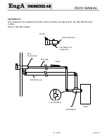
When
ordered,
factory
installed
pipe
chases
and/or
electrical
chases
are
built
into
the
unit
floor.
Factory
chases
are
provided
with
covers
that
need
to
be
replaced
and
sealed
after
piping
and
electrical
connections
are
made.
THE
FLOOR
OF
THE
UNIT
HAS
BEEN
MADE
WATER
‐
RESISTANT.
DO
NOT
CUT
OR
DRILL
HOLES
IN
THE
FLOOR
OR
USE
PENETRATING
FASTENERS.
All
penetrations
through
the
unit
walls
must
be
caulked
and
sealed
to
prevent
air
and/or
water
from
entering
the
unit.
ELECTRICAL
INSTALLATION
DO
NOT
install
anything
that
will
interfere
with
equipment
access
or
the
rating
plate.
The
unit
must
be
electrically
grounded
and
all
wiring
must
be
installed
in
accordance
with
the
National
Electrical
Code,
ANSI/NFPA
70,
and/or
the
Canadian
Electric
Code
CSA
22
‐
1
and
to
the
approval
of
the
authorities
having
jurisdiction.
THE
FLOOR
OF
THE
UNIT
HAS
BEEN
MADE
WATER
‐
RESISTANT.
DO
NOT
CUT
OR
DRILL
HOLES
IN
THE
FLOOR
OR
USE
PENETRATING
FASTENERS.
Field
wiring
diagrams,
internal
wiring
diagrams
and
operating
functions
are
included
in
the
control
cabinet.
The
power
requirements
are
indicated
on
the
rating
plate.
Where
field
wiring
of
control
circuits
is
required,
take
care
to
size
the
field
wiring
for
a
maximum
10%
voltage
drop.
The
control
circuit
ampacity
is
noted
on
the
field
wiring
diagram.
See
the
field
wiring
diagram
for
requirements
for
shielded
or
twisted
pair
wire
for
solid
state
devices.
Caution:
Temporary
Power
Generation
The
warranty
will
be
void
if
the
voltage
being
fed
from
any
temporary
generator
is
not
within
10%
of
the
nominal
rated
nameplate
voltage
and
voltage
imbalance
shall
be
limited
to
2%.
A
power
monitor
shall
be
installed
by
others
to
properly
monitor
power
quality
and
conditions.
All
generator
sets
shall
be
provided
with
overcurrent
and
earth
‐
fault
protection.
The
protective
apparatus
should
be
capable
of
interrupting,
without
damage,
any
short
‐
circuit
current
that
may
occur.
Warning:
No
unspecified
external
load
shall
be
added
to
the
control
transformer
circuit(s)
or
to
the
main
power
circuit(s).


