


16
010.1220.0719 01.21
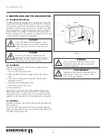
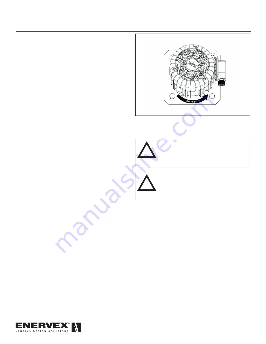
by an arrow on the motor end cover. There are holes in the
end cover that allow you to see the cooling vanes, but it is
hard to see the rotation unless the fan is running very slowly.
For a more precise determination, you can also look inside
the fan housing as shown in Fig. 15. The arrow shown (not
actually inside fan housing) shows the proper rotation. It
is possible for the fan to operate with improper rotation.
However, the fan will only provide 25–30% of full capacity, will
cause damage to components and should be avoided.
Fan rotation can be changed on the EDrive by switching the
attachment position of any two power leads.
4.11 INSTALLING A PROVEN FLOW SYSTEM
If required by local codes, a safety system can be interlocked
with the appliance(s) to prove fan operation. The safety
system could utilize a Proven Draft Switch (PDS), a thermal
switch, a flow switch or a sail switch. The device must be
interlocked with the appliance(s) so it shuts down in case of
fan failure or power failure.
Please refer to the PDS Installation Manual for wiring
instructions.
If the installation includes a MEC24 Exhaust Control or
EBC 30/31 Modulating Pressure Fan Control, a PDS is not
required as the function is integrated into the control.
For more information about alternative safety system, please
consult ENERVEX.
Fig 15
AVERTISSEMENT
La turbine doit impérativement tourner dans le bon
sens. Une rotation en sens inverse entraînerait de
mauvaises performances de soufflage, une surcharge
du moteur voire un grillage du moteur.
!
WARNING
Correct direction of wheel rotation is critical.
Reversed rotation will result in poor air performance,
motor overloading and possible burnout.
!
Summary of Contents for BEF 225x
Page 23: ...23 010 1220 0719 01 21...


