


14
010.1220.0719 01.21
voltage transients, typically originating from lightning strikes
or switching of high power equipment on the same supply.
When carrying out a HiPot (Flash) test on an installation
in which the drive is built, the voltage surge suppression
components may cause the test to fail. To accommodate
this type of system HiPot test, the voltage surge suppression
components can be disconnected by removing the VAR
screw After completing the HiPot test, the screw should
be replaced and the HiPot test repeated. The test should
then fail, indicating that the voltage surge suppression
components are once again in circuit.
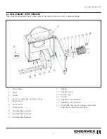
4.6 Electrical Connection of the Motor and EDrive
The motor should be connected to the EDrive E3 U, V, and
W terminals using a suitable 3 or 4 core cable. Where a 3
core cable is utilised, with the shield operating as an earth
conductor, the shield must have a cross sectional area at
least equal to the phase conductors when they are made
from the same material. Where a 4 core cable is utilised, the
earth conductor must be of at least equal cross sectional
area and manufactured from the same material as the phase
conductors.
The motor earth must be connected to one of the EDrive E3
earth terminals.
Maximum permitted motor cable length for all models: 100
meters shielded, 150 meters unshielded.
Where multiple motors are connected to a single drive using
parallel cables, an output choke must be installed..
The BEFx Fan sizes 225-355 require four (4) 14AWG
conductors between the EDrive and the Fan motor. (Three
(3) Power lines, and one (1) dedicated Ground wire.)
The BEFx Fan Sizes 225-800 require four (4) 12AWG
conductors between the EDrive and the Fan motor. (Three
(3) Power lines, and one (1) dedicated Ground wire.)
Make all necessary connections to the power and low-
voltage terminals (see wiring diagram).
4.7 Motor Terminal Box Connections
Do not install any mechanical or electro-mechanical switching
devices between the drive and motor. Where a local isolator
is installed close to the motor, this should be interlocked with
the drive control circuit to ensure the drive is disabled when
the motor is isolated.
Most general purpose motors are wound for operation on
dual voltage supplies. This is indicated on the nameplate
of the motor. This correct voltage setting must be selected
when installing the motor by selecting either STAR or DELTA
connection. STAR always gives the higher of the two voltage
ratings.
4.8 Wiring Diagram - BEF 225-355x / 1X120V
NOTE: All published voltages relate to power supplied to the
EDrive and NOT the motor.
BEF 225-355x fans operate at 1x120 VAC.
The wiring diagram in Fig. 14 is a typical wiring diagram for a
BEF 225-355x with 120V supply voltage to the motor drive.
The BEFx is listed with an EDrive motor controller which is
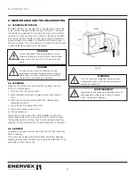
DANGER
This EDrive contains high voltage capacitors
that take time to discharge after removal of
the main supply. Before working on the drive,
ensure isolation of the main supply from line
inputs. Wait ten (10) minutes for the capacitors to discharge
to safe voltage levels. Failure to observe this precaution
could result in severe bodily injury or loss of life.
Cette EDrive contient des condensateurs à haute tension
qui mettent du temps à se décharger après le retrait de
l’alimentation principale. Avant de travailler sur le variateur,
veillez à isoler l’alimentation principale des entrées de
ligne. Attendez dix (10) minutes que les condensateurs se
déchargent à des niveaux de tension sûrs. Le non-respect
de cette précaution peut entraîner des blessures graves ou
la mort.
Fig 13
Summary of Contents for BEF 225x
Page 23: ...23 010 1220 0719 01 21...


