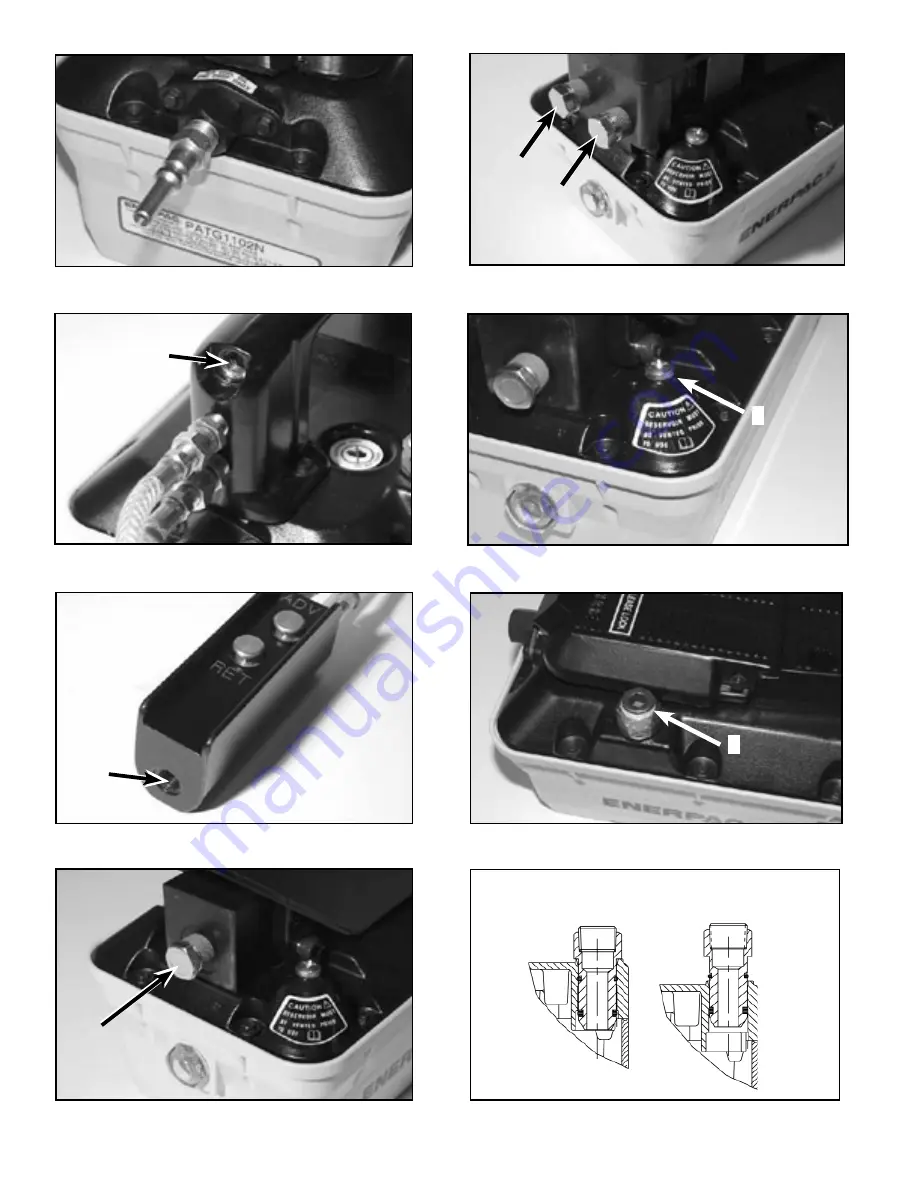
Figure 1
Figure 2
Figure 3
Figure 4
Figure 5
Figure 7A
Figure 7B
Figure 8
6
A
CLOSEDFerméGeschlosenChiusoCerrado
VENTEDAéréEntlüftetVentilazioneAbierto
1
2
B
図
8
图8
4
图4
3
图3
图2
图1
7B
图7B
7A
图7A
5
图5
出される
放气
閉鎖した
闭合
Page 1: ...ct steel or wood blocks that are capable of supporting the load Never use a hydraulic cylinder as a shim or spacer in any lifting or pressing application DANGER To avoid personal injury keep hands and...
Page 2: ...air pressure adjustment 5 2 Air Connections See Illustration 1 Attach air supply to the 1 4 NPT swivel connection on the end of the pump Use Teflon tape or similar thread sealant Torque to 20 25 ft l...
Page 3: ...ll port pull up the vent fill assembly past the first detent Then completely remove the assembly from the reservoir If oil level is low add oil as described in Section 5 6 To use as a return to tank p...
Page 4: ...e intake tube to refill the pressure chamber You may need to hold the treadle and throttle the PRESSURE button for a few minutes to completely remove the air and prime the pump models with an air pend...
Page 5: ...but load does not move Load greater than cylinder capacity at full pressure Flow to cylinder blocked 6 Cylinder drifts back on its own External system leak Internal leak in system component 7 Cylinde...
Page 6: ...igure 1 Figure 2 Figure 3 Figure 4 Figure 5 Figure 7A Figure 7B Figure 8 6 A CLOSED Ferm Geschlosen Chiuso Cerrado VENTED A r Entl ftet Ventilazione Abierto 1 2 B A 8 8 4 4 3 3 2 2 1 1 7B 7B 7A 7A 5 5...
Page 7: ...Figure 9 Figure 10 Figure 11 Figure 12 Figure 13 7 1 2 C B A A 10 10 11 11 9 9 12 12 13 13...