Enerpac DSX11000 Instruction Sheet Download Page 16

14


L4442

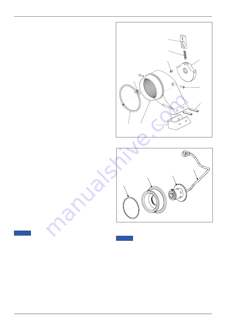
7.2.4  Reaction Arm - Disassembly and Reassembly


(Fig. 16)

Disassembly

1.

To remove the wire assembly (36) that is securing

the reaction arm to the wrench body, first unscrew

the wire assembly nut followed by the rest of the

assembly (36).

2.

Remove the reaction arm assembly, including the

retaining plate (4), and shackle ring (38).

3.

Unscrew the two plate screws (35) and remove

retainer  (24).

4.

Remove the grub screw (10), followed by the

retainer tab (15) and spring (16).

5.

If required, the shackle ring can be removed from

the reaction arm body by removing the eyebolt

assembly and separating the shackle ring arms.

6.

Clean all exposed components with a mild solvent.

7.

Inspect all parts for damage. 

Replace any worn or

damaged parts.

Reassembly and Installation

1.

Apply silicon lubricate to all components, except

the two plate screws (35).

2.

Re-assemble the spring (16), retainer tab (15), and

grub screw (10), applying a small amount of Loctite

222 thread sealant on to the grub screw before

installing the assembly into the retainer plate (24).

3.

Fit the retainer plate (24) into the reaction arm body

(2), apply a small amount of Loctite 243 thread

sealant to the threaded mounting holes before

inserting plate screws (35).

4.

If removed, reattach the shackle ring (38), secured

into place with the eyebolt. Loctite 222 should be

applied to the thread of the eyebolt during assembly.

5.

Install the wire assembly (36) into the rear of the

piston sleeve. Slide the reaction arm (2) onto the

wrench body (1), threading the end of the wire

assembly (36) through the retainer plate (24) and

secure by screwing the hex nut onto the end of the

wire assembly (36).

7.2.5  Square drive Release Button Disassembly 

and Reassembly (Fig. 17)

Disassemble the square drive release button 

only if it is not operating properly or if it is worn or 

damaged.
1.

Remove circlip (13).

2.

Separate the button mechanism (12)  from the

retaining block (14).

3.

Clean all parts with a mild solvent. Dry all parts

after cleaning.

4.

Inspect all parts for damage.

5.

Reassemble retaining button assembly (12) and

bushing (14) and secure with circlip (13).

6.

Apply a thin coat of molybdenum disulphide grease 

in the areas shown in Figure 10.


NOTICE

13

14

12

37

Figure 17: Exploded Square drive

38

35

33

25

24

16

15

10

2

(eyebolt thread 

only)

Figure 16: Exploded Reaction Arm

Apply Loctite 222 Thread Sealant

Apply Loctite 243 Thread Sealant

If a fault develops with the retaining button 

assembly (12), the whole assembly will need to be 

replaced. It is not recommended that this item be 

disassembled.


NOTICE

Summary of Contents for DSX11000

Page 1: ...L4442 Rev A 03 20 Dedicated Square Drive Torque Wrench DSX1500 DSX3000 DSX5000 DSX11000 DSX25000 ENGLISH EN Instruction Sheet...

Page 2: ...idiomas consulte www enerpac com www enerpac com F r andra spr k bes k www enerpac com www enerpac com CONTENTS 1 0 INTRODUCTION 1 2 0 SAFETY 1 2 1 SAFETY PRECAUTIONS 2 3 0 FEATURES AND COMPONENTS 5 4...

Page 3: ...id personal injury as well as damage to the product and or damage to other property Enerpac cannot be responsible for any damage or injury from unsafe use lack of maintenance or incorrect operation Do...

Page 4: ...he system is pressurized Be certain that all hose couplings are fully connected at both the pump and wrench ends before applying any hydraulic pressure If the couplings are not fully connected oil flo...

Page 5: ...rtical and inverted applications The torque required to loosen a nut is variable and may exceed the torque capacity of the wrench Never operate the wrench at above 75 percent of its rated maximum torq...

Page 6: ...jor source of ignition To help prevent the possibility of ignition resulting from excessive surface temperatures do not use the wrench in an environment with an ambient temperature of above 104 F 40 C...

Page 7: ...l the square drive in the location shown in Figure 3 For loosening bolts install the square drive on the opposite side of the wrench WARNING Right is tight Left is loose 4 0 CONNECTING THE TOOL 4 1 At...

Page 8: ...bursting or disconnecting under pressure High pressure oil leakage may also occur Serious personal injury could result The torque wrench and hydraulic pump are connected by a 10 000 PSI 700 Bar twin l...

Page 9: ...ting it on the application Cycling the tool ensures the system is operating properly and removes trapped air if any 2 Place the correct size impact socket on the square drive and secure properly with...

Page 10: ...shed periodically 5 Fittings should be kept clean and not allowed to be dragged along the ground or floor as even small particles of dirt can cause the internal valves to malfunction WARNING NOTICE Al...

Page 11: ...Surfaces LP7 Inner Surface LP13 All Surfaces LP2 Bearing Surface LP8 Bearing Surface LP14 Bearing Surface LP3 Wrench Body Inner Surfaces LP9 Bearing Surface LP15 Bearing Surface LP4 Square Drive Bear...

Page 12: ...nger tight Then wrench tighten the coupling an additional 2 to 3 turns beyond finger tight 6 Coat the threads on the swivel end of the female coupling B2 with Loctite 577 thread sealant Thread the cou...

Page 13: ...he Swivel Post and Swivel Assembly Fig 11 Attaching the Swivel Post 1 Apply a small amount of Loctite 243 thread sealant to the threaded mounting holes in the wrench housing See Fig 11 for locations 2...

Page 14: ...damage to these components and also may damage the sealing faces within the wrench NOTICE In the following steps lubricate all O rings with ISO 10 grade oil 1 Fit piston head o ring 31 into the piston...

Page 15: ...re placing the wrench into service Refer to the procedure in Section 7 2 4 7 2 3 Hydraulic Pressure Testing Connect hydraulic hoses and cycle the wrench at 1 000 psi 69 bar to check for oil leaks If t...

Page 16: ...ting holes before inserting plate screws 35 4 If removed reattach the shackle ring 38 secured into place with the eyebolt Loctite 222 should be applied to the thread of the eyebolt during assembly 5 I...

Page 17: ...e is broken Replace parts as necessary return to Enerpac Cylinder will not retract Voltage to electric pump is too low to line drop or inadequate amperage is available Get shorter extension cord If sh...

Page 18: ...rque Ft lbs 141 323 563 1152 2406 Nm 191 438 764 1562 3262 Weight lbs 4 85 10 58 17 86 31 75 71 65 kg 2 2 4 8 8 1 14 4 32 5 Dimensions A inch mm 1 73 44 2 28 58 2 72 69 3 43 87 4 61 117 B inch mm 2 64...

Page 19: ..._____________ ____________________________________________________________________________________ ____________________________________________________________________________________ ________________...

Page 20: ...www enerpac com 2020 Enerpac All Rights Reserved...

Reviews: