3
The selected pump or booster will operate at various desired
pressure ranges within its maximum rated capacity. Therefore, the
"Workholding Cylinders" will operate at many desired workholding
forces by merely regulating the hydraulic operating pressure (psi) of
the pumps or boosters.
5.0 INSTALLATION
1.
Install the booster in a location which is higher than the working
cylinders. The booster can be mounted in the horizontal or one
vertical position. When mounting vertically, the hydraulic output
end (port) must face up.
2.
To mount the booster, remove the capscrew and acorn nuts
securing the bracket to the booster.
3.
Re-position the booster bracket using any of the six positions
around the circumference of the booster. Be sure all capscrews
are firmly tightened.
4.
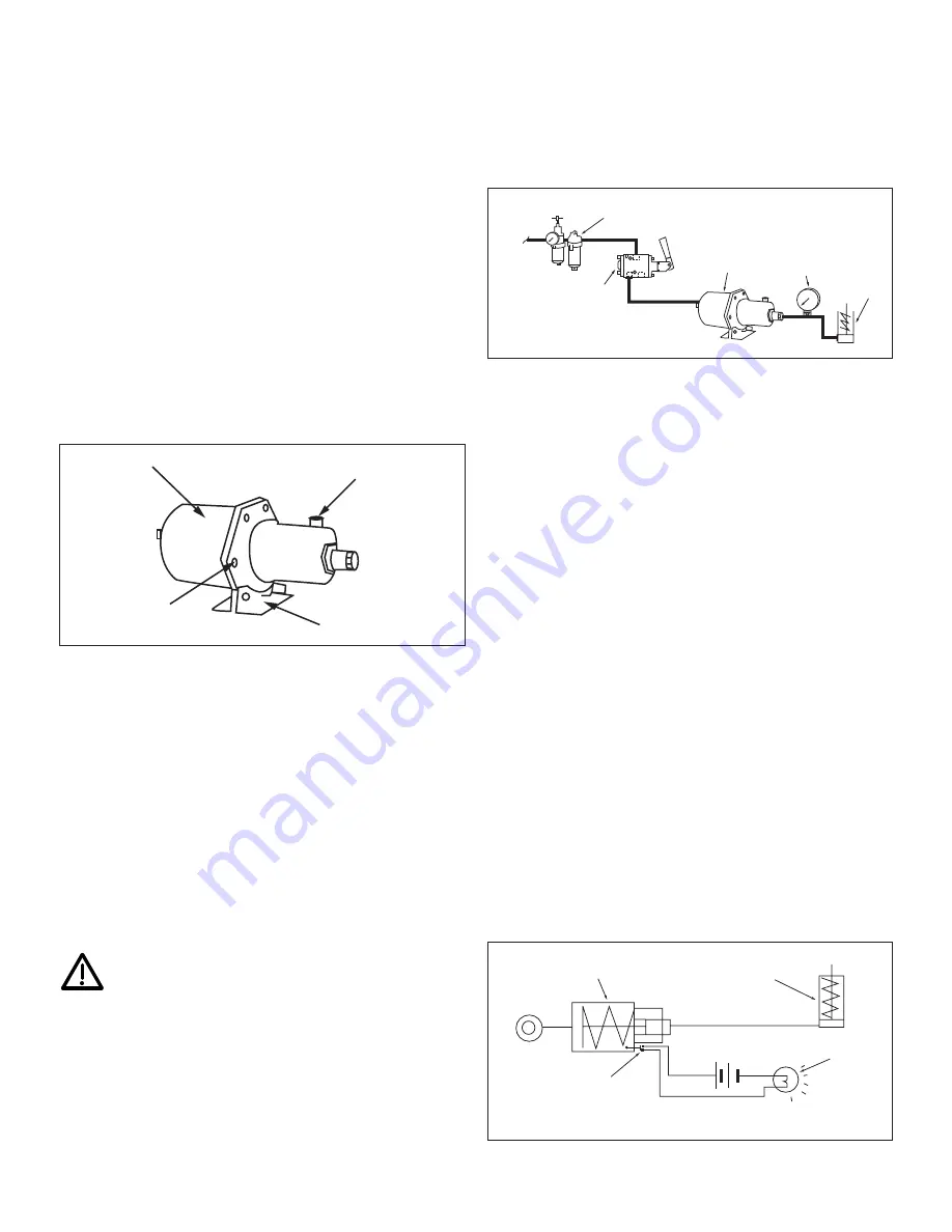
Install four mounting screws through the bracket and into the
mounting plate (figure 1).
Note:
When mounting the booster, the air fill cap and sight gauge
should always remain visible and useable to permit checking and
re-filling the reservoir.
Figure 1
6.0 INCOMING AIR SUPPLY
Compressed air, to the booster, must be clean, dry and lubricated to
protect the booster components. If properly treated air is not
available, install an Enerpac regulator/filter/lubricator in the air line
leading to the booster control valve. The regulator/filter/lubricator
provides the following advantages:
1.
Removes dirt and moisture from the air
2.
Provides a mist of lubrication in the air supply which protects
control valves and booster internal parts. Filter lubricators use
Enerpac hydraulic oil.
3.
Contains an air regulator valve and gauge to adjust air pressure
to the booster.
7.0 AIR AND OIL CONNECTIONS
Caution:
Teflon tape is an excellent thread sealer, however,
if not properly applied small pieces can tear loose and
enter the hydraulic system causing restrictions and
potential malfunctions. Use 1
1
/
2
wraps and leave the 2 threads, at
the end of fitting, without tape.
1.
A 3-way, 2-position directional control valve (VA-42) is required
to operate booster. Locate the valve within six feet of the
booster, between the regulator/filter/lubricator and the booster
inlet port. Valve port sizes are
3
/
8”
- 18 NPT.
2.
Connect the air supply line to the input port on the
regulator/filter/lubricator (
3
/
8”
- 18 NPT).
3.
Install an air line from the regulator/filter/lubricator outlet port to
the VA-42 valve, port No. 3 (
3
/
8”
- 18 NPT).
4.
Mount the VA-42 control valve to a solid base. Use the three
mounting holes in the valve body.
5.
Connect an air line from the VA-42 control valve, port No. 4, to
the booster inlet port (figure 2). Valve port No. 1 remains open
for exhausting air.
Figure 2
6.
Attach a hydraulic line from the booster to the system working
components (ie. cylinder, clamps or valves). Fill booster hydraulic
reservoir with ENERPAC oil, approximately 1.75 quart.
8.0 BOOSTER OPERATION
Booster operating speed depends on factors including working
cylinder strokes, valving, hose lengths and port sizes.
1.
Keep hose or pipe lengths reasonably short.
2.
Provide clean, dry, lubricated air supply at 40 psi minimum to
125 psi maximum.
3.
All hoses, fittings, piping and associated components must be
pressure rated to withstand maximum system pressure.
4.
Maintain booster oil level in the reservoir. Check sight gauge
frequently. Repair leaks immediately.
5.
Prior to operation, bleed system to remove air trapped in
hydraulic components.
6.
Bleeding Hydraulic System
(a) Check booster reservoir level. Fill to capacity.
(b) Activate booster to complete 2 or 3 cycles and pump oil
into entire system.
(c) Loosen a fitting (furthest from booster). Cover fitting with
rags to prevent oil splatter.
(d) Activate booster to full advance, tighten fitting,
retract booster.
(e) Add hydraulic oil to booster reservoir.
7.
MAGNETIC SENSOR: The sensor connections are available to
connect optional indicator lights or buzzers which actuate upon
completion of the hydraulic plunger stroke. Figure 3 illustrates
a typical light connection.
Figure 3
Cylinder
Lamp
Booster
Magnetic
Sensor
Cylinder
Gauge
Booster
VA-42
Valve
Filter
Lubrication
Hydraulic Line
5 3
2
4
Incoming
Air
Booster
Capscrews
Fill Cap
Mounting Bracket


