


2
WARNING:
Only use hydraulic cylinders in a coupled
system. Never use a cylinder with unconnected couplers.
If the cylinder becomes extremely overloaded,
components can fail catastrophically causing severe personal
injury.
WARNING: BE SURE SETUP IS STABLE BEFORE
LIFTING LOAD.
Cylinders should be placed on a flat
surface that can support the load. Where applicable, use a
cylinder base for added stability. Do not weld or otherwise
modify the cylinder to attach a base or other support.
Avoid
situations where loads are not directly centered on
the cylinder plunger. Off-center loads produce
considerable strain on cylinders and plungers. In addition,
the load may slip or fall, causing potentially dangerous results.
Distribute the load evenly across the entire saddle surface.
Always use a saddle to protect the plunger.
IMPORTANT:
Hydraulic equipment must only be serviced
by a qualified hydraulic technician. For repair service,
contact the Authorized ENERPAC Service Center in your
area. To protect your warranty, use only ENERPAC oil.
WARNING:
Immediately replace worn or damaged parts
by genuine ENERPAC parts. Standard grade parts will
break causing personal injury and property damage.
ENERPAC parts are designed to fit properly and withstand high
loads.
3.0 SPECIFICATIONS
Note:
Shipping box contains fittings for NPT hook-up. The fitting
with the tapered male threads goes into the 3/8 BSPT air inlet.
Ambient Temperature Range..............-4˚F (-20˚C) to +176˚F (80˚C)
Recommended Oil Temperature ......+59˚F (15˚C) to +131˚F (55˚C)
Minimum Operating Air Pressure ................................40 psi (3 bar)
Maximum Operating Air Pressure ..............................125 psi (9 bar)
Air Consumption ..............................................0.95 cu. ft. per stroke
Reservoir Capacity ..............................................................50 cu. in.
Usable Oil Capacity ..........................................................13.4 cu. in.
Maximum Cycle rate ........................................10 cycles per minute
Air Piston Retract Speed (from full extend)
@ 86 psi (6 bar)............................................................Max. 3.2 sec.
Return Spring Force @ Initial Position....................................57 lbs.
Return Spring Force @ Maximum Compression ..............1041 lbs.
Stroke Sensing Position Before Full Stroke ..........................1.04 in.
Sensing Contact Capacity ......................................30 VDC, 3 amps
4.0 INSTRUCTIONS
4.1 General Description
Air operated hydraulic boosters convert low pressure air to high
pressure hydraulic oil for operating hydraulic cylinders, clamps or
similar devices. Primary booster components are, the air piston and
the hydraulic cylinder plunger. Air pressure, into the booster, exerts
a force against the air piston causing it to move forward. The forward
motion compresses the piston return spring and moves the hydraulic
plunger in the oil cylinder. The plunger compresses the oil in the
cylinder developing high pressure at the outlet port.
Pressure intensification is determined by the air piston to hydraulic
plunger ratio. If the booster ration is 20:1 100 psi air pressure will
produce 2000 psi hydraulic pressure. Air pressure of 80 psi will
produce 1,600 psi hydraulic pressure. To determine actual holding
forces, multiply the effective area of a working cylinder by the
hydraulic pressure being produced.
The result is holding force
in pounds.
4.2 Selecting Cylinders and Boosters
1.
Determine the holding force required for the application.
2.
Determine input air pressure available.
3.
Determine volume of oil required in the hose or pipe from the
booster to the working hydraulic cylinder or clamping devices.
Note:
Any cylinder can be matched with any pump or booster as
long as the pump or booster has enough useable oil capacity (cubic
inches) to transmit and fully extend the cylinder or cylinders.
Your only other consideration is knowing the maximum Hydraulic
Pressure Range (psi) of the selected pump or booster for
determining the "Cylinder Holding Force" of the cylinder or
cylinders.
=
÷
OIL
Useable Oil
Capacity
Pump or
Booster
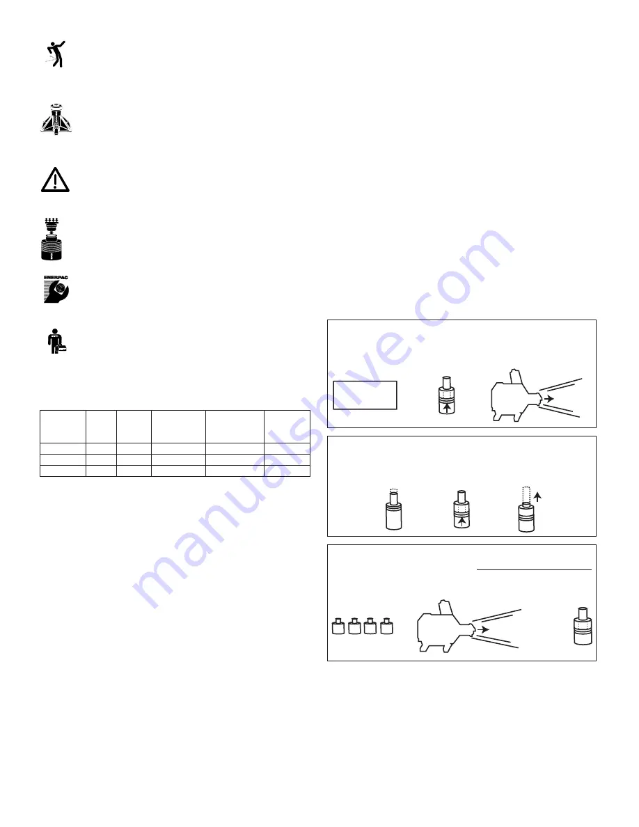
TO FIND:
Total number of Cylinders
Useable Oil Capacity of Pump
that can be used with = (or) Booster oil Output (cu. in.)
Booster or Pump
Oil Capacity of Cylinder (cu. in.)
OIL
=
x
TO FIND:
Cylinder Oil Capacity
=
Cylinder Effective
x
Cylinder Stroke
(cu. in.)
Area (sq. in.)
(inches)
=
x
Force
(lbs)
Pump or
Booster
Working
Pressure
TO FIND:
Cylinder Holding
=
Cylinder Effective
x
Hydraulic Working
Force (lbs)
Area (sq. in.)
Pressure (psi)
Model No.
Ratio
Oil
Per
Oil Pressure
Max
Piston
Stroke Oil
at 100PSI
Oil
Stroke
Output
Air Pressure
Pressure
B-2009
20:1
5.20 in.
9.30 cu. in.
2000 psi
2500 psi
B-3006
30:1
5.20 in.
6.20 cu. in.
3000 psi
3750 psi
B-5003
50:1
5.20 in.
3.70 cu. in.
5000 psi
6250 psi
®


