


17
EG-PMS2
PROGRAMMABLE USB SURGE PROTECTOR
All brands and logos are registered trademarks of their respective owners
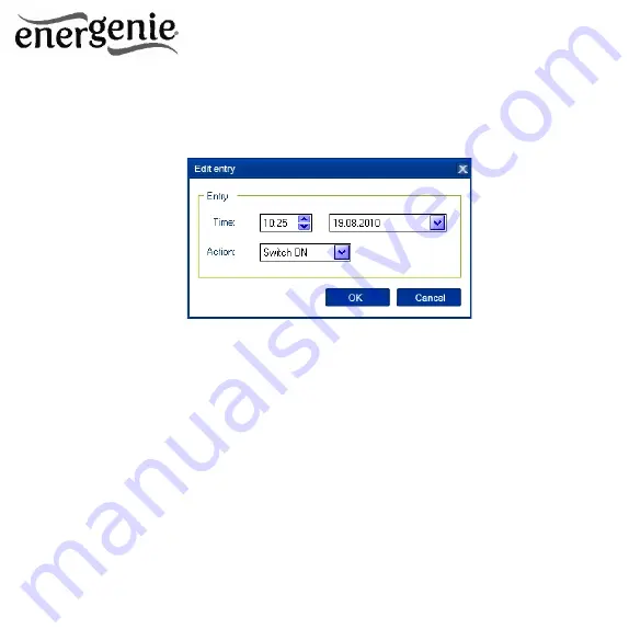
Figure #8
To remove the record, select it and click the
Remove
button (see
Figure #6 above). You can select multiple entries using
Ctrl
and
Shift
keys. You can also remove all entries from the schedule by clicking
the
Clear
button (see Figure #6 above)
To repeat your event (for example if you want to perform the same
events every day) use the
Loop
button (see Figure #6 above) and
specify the loop time period in the
Edit loop period
window (see
Figure #9 below)


