background image


6

Overview


Thank you for your purchase of the FNR‐4004 Embedded Digital Video Recorder (NVR). To get the most out of 
your NVR, please read through the


Installation’s


Manua

l and this


User’s


Manua

l thoroughly. 

 
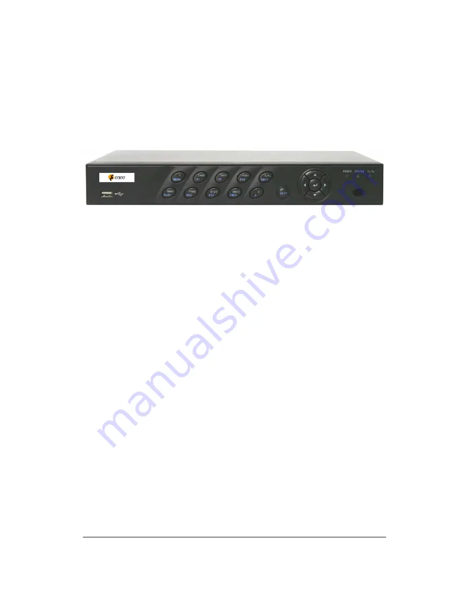
FNR‐4004 Embedded NVR, shown in Figure 1 ushers in the next generation of Network video recording 
technology from eneo. FNR‐4004 is a NVR model which only supports IP camera. Built on an embedded platform 

and combining the latest in advanced H.264 video encoding and decoding technologies, FNR‐4004 Embedded 
NVR contains the perfect combination of rock‐solid reliability and high performance. 


Fig 1: FNR‐4004 Embedded NVR 


Preventive


and


Cautionary


Tips


Before connecting and operating your NVR, please be advised of the following tips: 
• Ensure unit is installed in a well‐ventilated, dust‐free environment.   
• Unit is designed for indoor use only. 
• Keep all liquids away from the NVR. 
• Ensure environmental conditions meet factory specifications. 
• Ensure unit is properly secured to a rack or shelf. Major shocks or jolts to the unit as a result of dropping it may 
cause damage to the sensitive electronics within the unit.   
• Use the NVR in conjunction with an Uninterruptible Power Supply (UPS). 
• Power down the unit before connecting and disconnecting accessories and peripherals.


NVR


Specifications


Compression:


 Support PAL/NTSC video input. 

 Adopt H.264 video compression standard. 

 The FNR-4004 only supports IP camera. 

• Up to 2 Mega pixel (1920x1080) resolution is supported for IP camera. 
• Video encoding parameters of each channel can be set separately, including resolution, frame rate, bit rate,   
    image quality. 
• Each channel supports normal and event compression parameters. 
• Supports both composite stream and video only stream. Audio and video streams are strictly synchronized. 
• Supports watermark. 


Local


Functions


(Monitoring):


• Supports 1/4/9/16 screen live view, channel sequence is adjustable.   
• Supports live view group switch, manual switch and automatic cycle, the interval of automatic cycle can be   
    adjusted. 
• Supports digital zooming in live view mode 
• Supports shielding of an assigned live view channel. 
• Supports various PTZ protocols, PTZ preset, patrol and pattern. 
• Supports multi‐level user management, each user can have individual NVR access rights. 

• Supports mouse, front panel, and IR control. 


Local


Functions


(HDD


Management):


• Supports up to 1 SATA HDD, each HDD can support max 2TB capacity.


• Supports S.M.A.R.T. technology. 
• Supports HDD hibernation function. 
• Supports Windows compatible file system format and technology of pre‐allocating hard disk space to avoid   
    HDD fragments. 

Summary of Contents for FNR-4004/500

Page 1: ...User Manual Network Video Recorder 4 IP Channels H 264 FNR 4004 500...

Page 2: ...o 40 C and at a humidity of max 80 The unit should be protected against excessive heat dust damp and vibration Do not place any heavy objects on the unit To disconnect the power cord of the unit pull...

Page 3: ...ing Settings for Recording 28 Configuring Recording Settings 28 Configuring a Quick Recording Schedule 29 Configuring an Advanced Recording Schedule 30 CHAPTER5 Playback 32 Playing Back a Recording 33...

Page 4: ...agement 57 Managing Disks 58 Checking Disk Status 58 Formatting Disk 58 Enabling Disk Overwrite 59 Managing Files 60 Searching for Recorded Files 60 Locking and Unlocking Recorded Files 60 CHAPTER10 N...

Page 5: ...5 CHAPTER 1 Introduction...

Page 6: ...ply UPS Power down the unit before connecting and disconnecting accessories and peripherals NVR Specifications Compression Support PAL NTSC video input Adopt H 264 video compression standard The FNR 4...

Page 7: ...ports 10 100M adaptive network interface Supports TCP IP protocols DHCP DNS DDNS NTP and SADP etc Supports unicast and multicast support TCP UDP and RTP for unicast Supports remote search playback and...

Page 8: ...8 Connecting Your NVR You may follow the diagram below Figure 2 in connecting your NVR to its peripherals Fig 2 NVR Connection Diagram...

Page 9: ...e camera PLAY AUTO The PLAY AUTO button is used to enter the Playback menu It is also used to turn audio on off in the Playback menu and auto scan in the PTZ Control menu REC SHOT The REC SHOT button...

Page 10: ...iver operation by IR remote control Note It is important to note that you must click the EDIT button on either the remote or front panel on a text field before you re able to edit its content After yo...

Page 11: ...ontrol 3 Alphanumeric Buttons Same as Alphanumeric buttons on front panel 4 EDIT Button Same as EDIT button on front panel 5 A Button Same as A button on front panel 6 REC Button Same as REC button on...

Page 12: ...receiver is not obstructed Using a USB Mouse A regular 3 button Left Right Scroll wheel USB mouse can also be used with this NVR To use a USB mouse 1 Plug USB mouse into one of the USB ports on the f...

Page 13: ...13 Symbols Switch to symbols input Backspace Delete the character in front of the cursor Enter Confirm selection ESC Exit out of Soft Keyboard Figure 6 Soft Keyboard Buttons...

Page 14: ...14 CHAPTER 2 Getting Started...

Page 15: ...ng power 2 Connect the NVR to a VGA monitor You will only see the NVR menu system when it s connected to a VGA monitor 3 Press the POWER switch on the back rear panel The Power indicator LED should tu...

Page 16: ...Shutdown menu by going to Main Menu Maintenance Shutdown 2 Select the Lock button to lock the NVR or the Reboot button to reboot the NVR Setting Date Time It is extremely important to setup the system...

Page 17: ...heckbox 5 To acquire the time and date over an NTP Network Time Protocol Server check the Synchronize via NTP server checkbox You may enter your own NTP server or select from one of the default locati...

Page 18: ...ormation The model number of the NVR serial No the current firmware version installed on NVR etc Chan Status Cameras working status in NVR such as motion tampering video loss and video exception Recor...

Page 19: ...19 CHAPTER 3 Live Feed...

Page 20: ...current channel is recording There cording may have been started manually from a schedule and or triggered from motion or alarm Picture Settings Icon Adjust picture settings for selected display PTZ C...

Page 21: ...of a display 1 Select display 2 Click the Picture Settings icon This will bring up the Picture Settings menu as shown in Figure 15 Figure 15 Picture Settings Menu 3 Increase decrease amount for brigh...

Page 22: ...Select display to enable disable audio 2 Enable audio by clicking the Enable Audio icon and disable audio by clicking the Disable Audio icon An error message similar to the one shown in Figure 17 wil...

Page 23: ...enu 2x2 Mode Click to switch to four channel display mode 3x3 Mode Click to switch to nine channel display mode 4x4 Mode Click to switch to sixteen channel display mode Main Menu Click to go to NVR Ma...

Page 24: ...in the Display Configuration menu Note After 20 seconds of inactivity the NVR will automatically exit out of the Display menu and go back into the Live Feed mode Note The Lock Main Menu setting is sel...

Page 25: ...n Screen configuration of each video output You may select between a 1x1 2x2 3x3 or 4x4 configuration only 1x1 option is available if select Auxiliary Sequencing Dwell Time The time in seconds to dwel...

Page 26: ...creen configuration will have a selection box containing a list of the different cameras that are available on the NVR Pressing the up and down button of each selection box select the camera you would...

Page 27: ...27 CHAPTER 4 Record Settings...

Page 28: ...is the recording quality settings To configure the recording quality settings 1 Enter the Recording Quality Settings menu by going to Main Menu Recording Configuration Recording Quality Settings The...

Page 29: ...the Quick Schedule Configuration menu shown in Figure 23 by going to Main Menu Recording Configuration Quick Schedule Configuration Figure 23 Quick Schedule Configuration Menu 2 Select the camera to c...

Page 30: ...o Sunday to configure schedule for 5 Setup time periods for schedule If the 24HR checkbox is checked recording will occur over the entire day To setup multiple time periods uncheck 24HR and enter the...

Page 31: ...e settings and select Exit to return to the previous menu Selecting the Exit button without clicking Save will quit out of the menu without saving settings Note Creating a schedule in the Quick Schedu...

Page 32: ...32 CHAPTER 5 Playback...

Page 33: ...Playback Controls Controls for playback of the selected recording Clip Backup Tools Tools to backup clips from a recording Clip playback controls control for playback of marked clip Searching for Reco...

Page 34: ...trols to navigate through the recording The controls found under Playback Controls include Play Button Button to playback recording Pause Button Button to pause recording Decrease Speed Button Button...

Page 35: ...u to the original playback mode 6 Click the Enable Disable Audio button to turn on and off audio during playback 7 Click the Digital Zoom button to enable digital zoom Once enabled the regular recorde...

Page 36: ...36 CHAPTER 6 Backup...

Page 37: ...lay Clip Button Play the selected video clip Save Clip Button Save the selected video clip to the HDD Clear Clip Button Clear the selected video clip To select video clips in the Playback Interface 1...

Page 38: ...D writer by going to the Backup menu To backup video clips 1 Enter the Clips Backup menu shown in Figure 34 by first going to Main Menu Playback In the Playback menu click the Clips Backup button Figu...

Page 39: ...lect the files you would like to backup by checking the box next to the file You may also check the All File box to backup all files The total required space will be shown next to Total Size 3 Click t...

Page 40: ...40 CHAPTER 7 System Configuration...

Page 41: ...ic DNS allows you to create a hostname and associate it to your IP address making access to your NVR over the internet easier To configure DDNS 1 Enable DDNS by checking the DDNS checkbox 2 Select a D...

Page 42: ...selected remote user These functions include Log Search View logs that are saved on the NVR Serial Port Control Configure settings for RS232 and RS485 ports Two Way Audio Ability to use two way radio...

Page 43: ...2 Select a user to delete in the Remote Users List panel 3 Click the Remove button to delete user 4 Click the OK button to confirm deletion of user 5 Click the Done button to exit menu Editing a User...

Page 44: ...camera to configure in the camera drop down menu on the upper left of the menu If all cameras are to be configured with the same settings select All Cameras from the list 4 Configure PTZ settings inc...

Page 45: ...ust first be configured before PTZ presets patterns and patrols can be customized To customize PTZ presets 1 Enter the PTZ Configuration menu shown in Figure 42 by going to Main Menu System Configurat...

Page 46: ...position 8 Click the Done button to exit out of the PTZ Configuration menu To customize PTZ patrols 1 Enter the PTZ Configuration menu shown in Figure 42 by going to Main Menu System Configuration PTZ...

Page 47: ...part of the motion detection region Dragging or left clicking on areas that overlap the current selected motion detection area will include them into the region You may also click the Full Screen but...

Page 48: ...s checkbox to enable trigger events for the selected camera Uncheck the checkbox to disable trigger events 5 Select the trigger inputs that you would like to associate with the selected camera 6 Selec...

Page 49: ...t of the menu without saving settings Configuring Exceptions Actions can also be triggered when the NVR detects certain exceptions To setup exception configuration 1 Enter the Exception Configuration...

Page 50: ...ble the User Name and Password fields User Name User name to use for server authentication Password Password to use for server authentication SMTP Server Address for SMTP server SMTP Port Port for SMT...

Page 51: ...51 CHAPTER 8 Camera Management...

Page 52: ...m the list 3 Click Enable Privacy Zones 4 Up to four privacy zones can be used per camera and are shown using four different colors yellow green blue and pink Using the mouse click and drag out rectan...

Page 53: ...to enable video tampering detection on Press the Clear button to clear region 6 Select Actions to take if video tampering is detected More than one action can be selected per channel These actions inc...

Page 54: ...one action can be selected per channel These actions include Sound Audio Warning NVR will sound an audio warning if video loss is detected Pop up Image on Monitor NVR will show the corresponding chan...

Page 55: ...meras are to be configured with the same settings select All Cameras from the list 3 Configure OSD settings including Camera Name Name of selected camera Display Camera Name Enable to display camera n...

Page 56: ...e Cameras menu shown in Figure 50 by going to Main Menu Cameras Setup Add Remove Cameras Figure 50 Add Remove Cameras Menu 2 If an IP camera and NVR are in same LAN IP cameras will be automatically pr...

Page 57: ...57 CHAPTER 9 Disk Management...

Page 58: ...disks combined 3 Click the Done button to exit out of Disk Management Formatting Disk A newly installed hard disk drive HDD must be first formatted before it can be used with your NVR Formatting the d...

Page 59: ...to exit out of Disk Management Enabling Disk Overwrite Enabling disk overwrite will allow the NVR to overwrite the installed disks once the disks are full To enable disk overwrite 1 Enter the Disk Man...

Page 60: ...File type includes Locked and Unlocked files 7 Click the Search button or if you would like to search for only locked files Search All Locked Files button 8 A list of results with your search criteria...

Page 61: ...61 CHAPTER 10 NVR Management...

Page 62: ...port on the NVR 3 Click the Refresh button The contents of the USB storage device will be shown on the screen 4 Select the firmware file The firmware file is named digicap mav 5 Click the Upgrade butt...

Page 63: ...Export Import Configuration menu shown in Figure 59 by going to Main Menu Maintenance Export Import Configuration Figure 59 Import Export Configuration Menu 2 Connect the USB storage device to a USB p...

Page 64: ...Configuration 2 Connect the USB storage device to a USB port on the NVR 3 Click the Refresh button The contents of the USB storage device will be shown on the screen 4 Select the configuration file Th...

Page 65: ...rm Exception Operation and Information 4 Click the Search button The search results will be disabled in a list on the right side of the menu Figure 61 If there are more than 2000 entries click the Pre...

Page 66: ...ick the Set button 3 Select the menus you would like to lock unlock by selecting the Lock icon beside the menu s name in the list on the right You may also choose to lock and unlock all settings or ju...

Page 67: ...BS Monitor outputs VGA 1Vp p C VBS 75ohms BNC Spot monitor no Remote access remote software browser Recording alarm contact movement timer permanent Alarm inputs 4 Alarm output 1 Pre alarm recording u...

Page 68: ...68 Technical changes reserved...

Reviews: