background image

User’s Manual 


30 


RTSP 


Highlight 

RTSP

 and press the 

 button.  The RTSP setup


screen displays. 


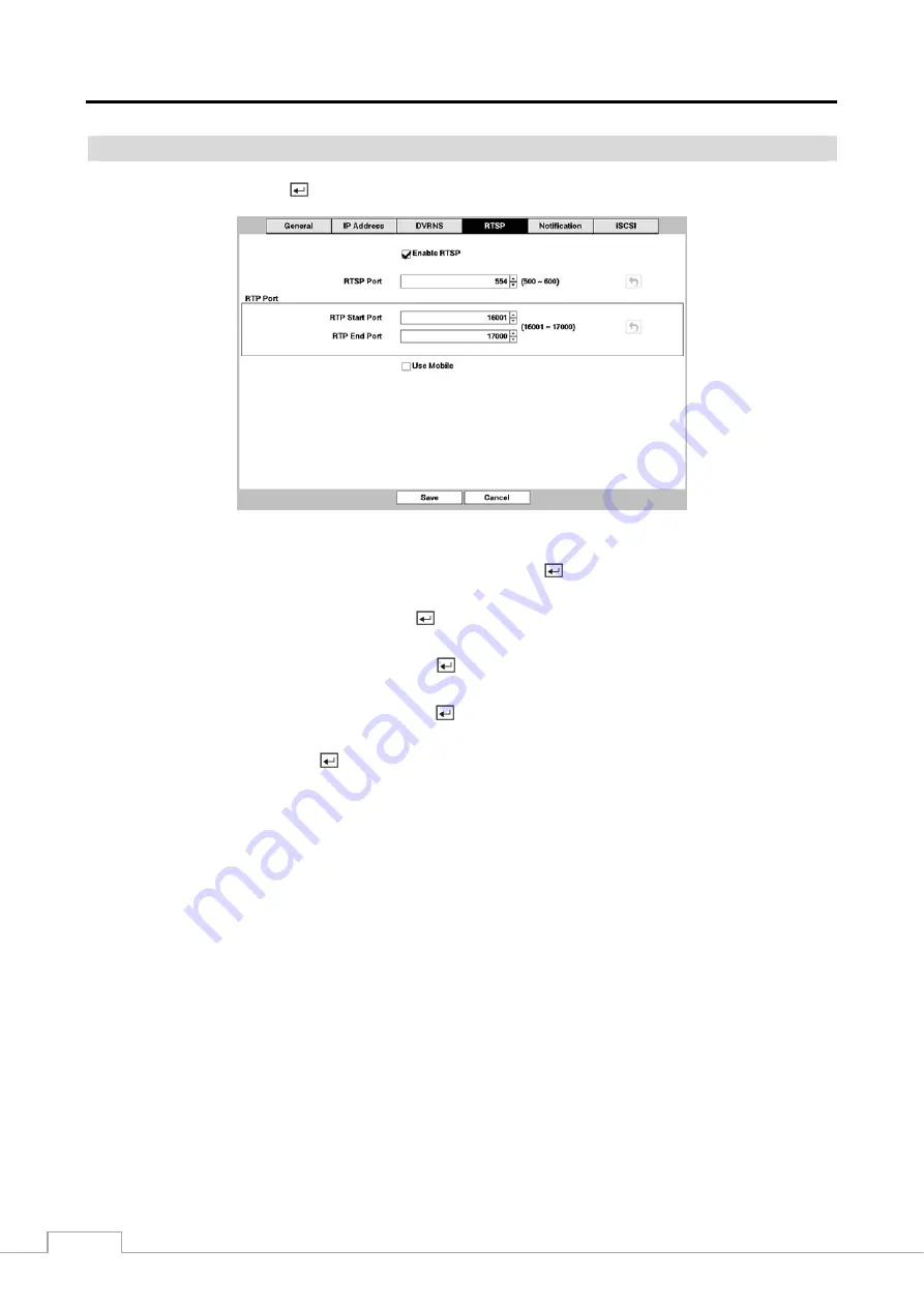
Figure 21 :  Network – RTSP setup screen. 


Highlight 

Enable RTSP

 (Real-Time Streaming Protocol) and press the   button to toggle between On and Off.  You 

will be able to change the settings if Enable RTSP is enabled. 


Highlight the box beside 

RTSP Port

 and press the 

 button.  Set the port number of the RTSP server obtained from 

your system administrator. 


Highlight the box beside 

RTP Start Port

 and press the 

 button.  Set the start port number of the RTP server obtained 

from your system administrator. 


Highlight the box beside 

RTP End Port

 and press the 

 button.  Set the end port number of the RTP server obtained 

from your system administrator. 


Highlight 

Use Mobile

 and press the 

 button to toggle between On and Off.  When set to on, you can access a remote 

DVR using a Blackberry or other mobile devices. 
 

NOTE: Selecting 

Use Mobile

 sets the WebGuard service to be enabled automatically regardless of your WebGuard 

settings.


You can access a remote DVR and monitor live video images using media players, such as VLC Player, 
supporting RTSP service.  Start the media player on your local PC and enter “rtsp://ID:Password@IP 
address:RTSP port number/track ID=‘channel number’”, or start Internet Explorer on your Blackberry 
or other mobile devices and enter “http://IP address:Webguard port number/”. 


RTSP service might not be supported, depending on the type of media player. 

Summary of Contents for DMR-5008/500

Page 1: ...Operating Instructions Digital Video Recorder H 264 Models DMR 5008 500 8 Channel DMR 5016 500 16 Channel ...

Page 2: ......

Page 3: ...NERATES USES AND CAN RADIATE RADIO FREQUENCY ENERGY AND IF NOT INSTALLED AND USED IN ACCORDANCE WITH THE INSTRUCTION MANUAL MAY CAUSE HARMFUL INTERFERENCE TO RADIO COMMUNICATIONS OPERATION OF THIS EQUIPMENT IN A RESIDENTIAL AREA IS LIKELY TO CAUSE HARMFUL INTERFERENCE IN WHICH CASE USERS WILL BE REQUIRED TO CORRECT THE INTERFERENCE AT THEIR OWN EXPENSE WARNING CHANGES OR MODIFICATIONS NOT EXPRESSL...

Page 4: ...echnician to restore the equipment to its normal operation E If the equipment has been dropped or the cabinet damaged F When the equipment exhibits a distinct change in performance this indicates a need for service 15 Replacement Parts When replacement parts are required be sure the service technician has used replacement parts specified by the manufacturer or that have the same characteristics as...

Page 5: ... Video Out 6 Power Cord Connector 7 Chapter 3 Configuration 8 Front Panel Controls 8 Camera Buttons 1 to 16 9 Enter Button 9 Arrow Buttons 9 Menu Button 9 ZOOM Button 10 PTZ Button 10 Panic Button 10 LED 10 Display Button 10 Monitor Button 10 Bookmark Button 10 Freeze Button 10 Alarm Button 10 Playback Buttons 10 Jog Dial Shuttle Ring 11 USB Port 11 ID Button on Remote Control 11 Sequence Button o...

Page 6: ... Device Setup 39 Audio 39 Alarm Out 39 Remote Control 40 Display Setup 41 OSD 41 Primary Monitor 42 Secondary Monitor 43 Spot Monitor 44 Status Setup 45 Event 45 Storage 46 Camera Setup 47 General 47 PTZ 47 Chapter 4 Operation 49 Turning on the Power 49 Live Monitoring 49 Live Monitoring Menu 50 Active Cameo Mode 51 Zoom Mode 52 PTZ Mode 52 Event Monitoring 53 Covert Camera 53 Spot Monitoring 54 R...

Page 7: ... Connector Pin Outs 76 I O Connector Pin Outs 76 RS485 Connector Pin Outs 76 Map of Screens 77 Troubleshooting 78 Specifications 78 List of Illustrations Figure 1 Typical DVR installation 2 Figure 2 16 Channel DVR rear panel 3 Figure 3 16 Channel DVR front panel 8 Figure 4 Infrared remote control 9 Figure 5 Login screen 12 Figure 6 Logout screen 12 Figure 7 Setup screen 13 Figure 8 System General ...

Page 8: ...e Alarm Out setup screen 39 Figure 32 Device Remote Control setup screen 40 Figure 33 Display OSD setup screen 41 Figure 34 Display Primary Monitor setup screen 42 Figure 35 Display Secondary Monitor setup screen 43 Figure 36 Display Spot Monitor setup screen 44 Figure 37 Status Event setup screen 45 Figure 38 Status Storage setup screen 46 Figure 39 Camera General setup screen 47 Figure 40 Camera...

Page 9: ... Time Synchronization using industry standard protocol y Built in DVD RW Drive y IR Remote Control y Self diagnostics with automatic notification including hard disk drive S M A R T protocol Technical Overview In addition to replacing both a time lapse VCR and a multiplexer in a security installation your DVR has many features that make it much more powerful and easier to use than even the most ad...

Page 10: ...xternal hard disk drives and there are two USB ports that can be used to upgrade the system or copy video clips to external hard disk and flash drives Figure 1 Typical DVR installation NOTE This manual covers the 8 and 16 channel digital video recorders The DVRs are identical except for the number of cameras and alarms that can be connected and the number of cameras that can be displayed For simpl...

Page 11: ...red to install the DVR Refer to the installation manuals for the other items that make up part of your system Figure 2 16 Channel DVR rear panel Video Input Video Loop Through Factory Reset Switch HD SD Out Selector Network Port iSCSI Port eSATA Port RS232C Port RS485 Port Alarm Input Output Audio In Out Video Out Power Cord Connector Your DVR can be used with either NTSC or PAL equipment NOTE You...

Page 12: ...inal settings it had when it left the factory HD SD Out Selector A HD SD Out selector is provided to select the monitor display mode between HD High Definition and SD Standard Definition Setting the selector to the HD OUT position sends HD video to the connected HDMI and VGA monitors and setting to the SD OUT position sends SD video to the connected composite BNC monitor Network Port The DVR can b...

Page 13: ...hole below the button After releasing the button tug gently on the wire to make certain it is connected To disconnect a wire press and hold the button above the wire and pull out the wire AI 1 to 16 Alarm In You can use external devices to signal the DVR to react to events Mechanical or electrical switches can be wired to the AI Alarm In and GND Ground connectors The threshold voltage of electrica...

Page 14: ...on Examples HD Display Mode SD Display Mode NOTE Connect the monitor before the DVR boots so that video can be displayed on the monitor with the resolution you have set during system setup Your DVR can record audio from up to 16 sources Connect the audio sources to Audio In 1 to Audio In 16 as needed using RCA jacks Connect Audio Out to your amplifier Use the provided audio extension cable to conn...

Page 15: ...T INSTALL POWER CORDS UNDER RUGS OR CARPET THE POWER CORD HAS A GROUNDING PIN IF YOUR POWER OUTLET DOES NOT HAVE A GROUNDING PIN RECEPTACLE DO NOT MODIFY THE PLUG DO NOT OVERLOAD THE CIRCUIT BY PLUGGING TOO MANY DEVICES IN TO ONE CIRCUIT Your DVR is now ready to operate Refer to Chapter 3 Configuration and Chapter 4 Operation Connect the AC power cord to the DVR and then to a wall outlet ...

Page 16: ...like a VCR combined with a multiplexer Many of the buttons have multiple functions The buttons on the infrared remote control while laid out differently perform the same functions as those on the front panel The following describes each button and control Take a few minutes to review the descriptions You will use these to initially set up your DVR and for daily operations NOTE The infrared sensor ...

Page 17: ...s are used to navigate through menus and GUI You can also use them to change numbers by highlighting a number in the menu and using the Up and Down arrow buttons to increase or decrease the number s value These buttons are also used to control Pan and Tilt when in the PTZ mode Menu Button Pressing the MENU button enters the Setup screen You will need to enter the authorized user and password to ac...

Page 18: ...is recording or searching video on the hard disk drive Display Button Pressing the DISPLAY button toggles between different display formats The available formats are 2x2 3x2 3x3 4x3 or 4x4 2x2 or 4x4 on a Spot Monitor Monitor Button Pressing the MONITOR button toggles the monitor selection between Primary MONITOR 1 on the remote control Secondary MONITOR 2 and Spot MONITOR 3 You can select the scr...

Page 19: ...ockwise plays video forward Turning the ring counterclockwise plays video backward Playback speed varies with the amount the ring is turned The playback speeds are x0 5 and When you release the ring it snaps back to the center position and the video pauses USB Port Two USB ports on the front panel are provided to connect external hard disk or flash drives for video clip copying or system upgrades ...

Page 20: ...ton to exit the screen Press the MENU button or move the mouse pointer to the top of the screen and then select Login in the Live Monitoring menu to enter the setup screens The Login screen appears Select a User and enter the password by pressing the appropriate combination of Camera number buttons and then the button There is no default password when logging in the admin user for the first time F...

Page 21: ...en making these entries a Virtual Keyboard will appear Use the arrow keys to highlight the character you want in the name or title and press the button That character appears in the title bar and the cursor moves to the next position Pressing toggles between the upper and lower case keyboards backspaces and deletes entered characters Special characters can be created using and a capital letter e g...

Page 22: ...iple DVRs with System ID 0 that are in the same area as long as they are not part of an RS485 network If this is the case all will be controlled at the same time when using the infrared remote control Highlight the box beside Language and press button A drop down menu displays the available languages Highlight the desired language and press the button The box beside Version displays the software v...

Page 23: ...he USB device NOTE Even after changing the DVR settings by importing saved settings the time related settings Date Time Time Zone and Daylight Saving Time will NOT be changed CAUTION The USB device must be FAT16 or FAT32 format Highlight Show System Log and press the button to display the System Log The System Log screen lists system activities up to 5 000 from the latest that have occurred along ...

Page 24: ... date and year Once you have the correct date press the button Highlight the Format box beside Date and press the button Select from the three available date formats and press the button to save your selected format Highlight the first box beside Time and press the button The individual sections of the time will highlight Use the Up and Down arrow buttons to change the number Use the Left and Righ...

Page 25: ...s the button Pressing the button toggles between On and Off When it is On the DVR you are setting up will run as a time server Highlighting Holiday and pressing the button displays the Holiday screen You can set up holidays by highlighting and pressing the button The current date appears Highlight the month and day and change them by using the Up and Down arrow buttons Press the button to add the ...

Page 26: ...The user can upgrade the software on a local system or a PC running RAS y Color Control The user can control brightness contrast hue and saturation for cameras on a local system or a PC running RAS y System Check The user can view the remote system status or check the remote system status as a batch process on a PC running RAS y PTZ Control The user can control the PTZ camera on a local system or ...

Page 27: ...g Archive or not Not Using Not formatted indicates the device is not formatted indicates when the device has temporary space set aside so that video clips can be saved on a DVD RW Highlight the box in the Format column for the desired storage device and press the button You will be able to format the device for recording or archiving When selecting Not Using from Use As and highlighting the Format...

Page 28: ...ighlight Monitoring and press the button and the Monitoring setup screen appears Figure 12 System Monitoring setup screen The DVR can be configured to run self diagnostics and report the results Highlight the Settings box beside the desired event System Check Recording Check Alarm In Disk Almost Full Disk Bad or Disk Temperature and press the button Highlight the Settings box beside System and pre...

Page 29: ...e button System events can be associated with an Alarm Out connector sound the DVR s internal buzzer and or notify a number of different devices NOTE Alarm Out action cannot be set to System and Panic Record events Mail notify is the only option available for the System event For the Notify action to work the DVR should be registered in the RAS Remote Administration System Recording Setup General ...

Page 30: ...onger than the preset Limit Time Lapse Recording period the DVR records over the oldest video data time lapse or event video as it would in the Recycle mode even if this feature is turned On The maximum storage time is only an estimate because the amount of space required to store video varies depending on many factors such as motion and image complexity CAUTION When more than one disk is installe...

Page 31: ...ge heading and press the button to change the time range that the scheduled recording will take place The smallest time segment you can use is 15 minutes Highlight the box under the Mode heading and press the button to change the recording mode that will be used Choose from No Record Time Event and Time Event Simple Mode Only When the DVR is in the No Record mode it will not record during the pres...

Page 32: ...rom each other However the ips will be reset to the supported maximum value when the ips Quality Resolution and Dwell are all set to the highest value Advanced Mode Only Highlight the box under the heading and press the button to delete the recording settings You will be asked to confirm that you want to delete the settings Highlight Default and press the button The Default screen appears Highligh...

Page 33: ... Off for pre event recording The image speed can be set from 1 00 to 30 00 ips 25 00 ips PAL image quality can be selectable from Very High High Standard and Basic and image resolution can be selectable from Very High D1 High Half D1 and Standard CIF You can set the amount of time to record prior to the event by adjusting the Dwell You can set the Dwell from 5 seconds to 30 minutes The longer the ...

Page 34: ...ral setup screen displays Figure 18 Network General setup screen Highlight the first box beside Remote Watch bps ips Press the Up and Down arrow buttons to set the Transfer Speed from 50Kbps to 1Gbps Highlight the second box beside Remote Watch bps ips You can select the unit of measure for the transfer speed between bps and ips Press the button to set the transfer speed Highlight the box beside R...

Page 35: ...cept video and audio transmitted for remote monitoring or remote recording can be enhanced by using the SSL Secure Sockets Layer authentication When using the SSL function the DVR cannot be connected with a remote program or a network keyboard which does not support the SSL function CAUTION The remote connection will be disconnected temporarily after changing the SSL settings NOTE This product inc...

Page 36: ...t programs otherwise the DVR cannot be connected with the PC running RAS or WebGuard CAUTION When changing the port settings you must change the port settings on the PC running RAS as well Refer to the RAS manual for details Selecting DHCP from the Type and highlighting Save button reads the current IP address of the DVR configured by DHCP Dynamic Host Configuration Protocol network Selecting ADSL...

Page 37: ... when setting up the LAN Highlight the box beside Port and press the button Set the port number of the DVRNS server using the Up and Down arrow buttons to increase or decrease the numbers Highlight Use NAT and press the button to toggle between On and Off NOTE When using the NAT Network Address Translation device refer to the NAT manufacturer s instructions for the proper network settings Highligh...

Page 38: ...t and press the button Set the end port number of the RTP server obtained from your system administrator Highlight Use Mobile and press the button to toggle between On and Off When set to on you can access a remote DVR using a Blackberry or other mobile devices NOTE Selecting Use Mobile sets the WebGuard service to be enabled automatically regardless of your WebGuard settings You can access a remo...

Page 39: ...he IP address or domain name of the SMTP server NOTE You will need to get the IP Address or domain name of the SMTP Server from your network administrator You can use the domain name instead of IP address if you already set up the DNS Server when setting up the LAN Highlight the box beside Port and press the button Use the arrow buttons to enter the SMTP Server port number obtained from your syste...

Page 40: ...f Highlight the DVR Initiator Address box and press the button Use the arrow buttons to enter the IP address of DVR NOTE You will need to get the IP address from your network administrator Do NOT use the same IP address for the Initiator Address set here and IP address set during Network IP Address setup otherwise the iSCSI changes will not be saved Highlight the DVR Initiator Node Name box and pr...

Page 41: ...ight Use and press the button to toggle between On and Off Highlight the box beside User Password and press the button A virtual keyboard appears allowing you to enter the user ID and password NOTE Setting up the Authentication will be required to access the iSCSI device that uses the CHAP Authentication function The box beside Session displays the current connection status between the DVR and iSC...

Page 42: ... set up motion detection zones by selecting or clearing blocks NOTE You can set up motion zones one block at a time in groups of 8 individual block groups A block group is positioned within the image area using the Up and Down arrow buttons and individual blocks within the block groups are selected or cleared using the camera buttons Press the button to display the menu screen The menu on the setu...

Page 43: ...s ranging from 1 to 5 seconds or Never appears The DVR will not log and notify motion events occurred during the preset interval range NOTE The record action for motion events will not be affected by the Motion Ignoring function Highlighting Daytime Setup and pressing the button allows you to set up the Daytime range Highlight the box beside Daytime and press the button Use the Up and Down arrow b...

Page 44: ...can be associated with another camera trigger an Alarm Out connector sound the DVR s internal buzzer notify a number of different devices move PTZ cameras to preset positions and or display a camera on a SPOT monitor The DVR checks to see if anything is obscuring the camera Highlight the box beside Check Obscuration and press the button A list of sensitivity ranging from 1 to 10 or Never appears T...

Page 45: ...her camera trigger an Alarm Out connector sound the DVR s internal buzzer notify a number of different devices move PTZ cameras to preset positions and or display a camera on a SPOT monitor Highlight Use Ignoring Time and press the button to toggle between On and Off When set to On the DVR will ignore video blind events occurred during the preset period Highlighting Time Setup and press the button...

Page 46: ...ion End string Refer to the device manufacturer s documentation for the text string that the device sends when a transaction ends Highlight the more line s box and press the button Select the number of additional lines of text that you want the DVR to record You can choose from 0 to 10 Highlight the box beside Line Delimiter and press the button Use the virtual keyboard to enter the character s th...

Page 47: ...ure 30 Device Audio setup screen The DVR can record up to 16 audio inputs Highlight the box beside the input and press the button A list of cameras appears and you can select which camera you want associated with that audio input Highlight Enable Audio Out and press the button This toggles between enabling and disabling audio out Alarm Out Highlight Alarm Out and press the button The Alarm Out scr...

Page 48: ...pressing the button allows you to set how the alarm reacts during the scheduled time When set to On the Alarm Out is active during the scheduled time When set to Event the Alarm Out is only active when there is an Event during the scheduled time Highlighting the boxes under the Channels box and pressing the button allows you to set which alarm outputs will be active You can also select the DVR s i...

Page 49: ... the DVR is not in the Recycle mode y Archive The icon displays when the DVR is archiving recorded data y Mirror The icon displays when the DVR is disk mirroring y Date Time The current date and time information displays y User Name The name of the current user logged in displays y Background Panel The background panel at the bottom of the screen displays in black y Camera No The camera number dis...

Page 50: ...ot be used in the 4x4 display mode of the 16 channel and 3x3 mode of the 8 channel DVR You can adjust the display dwell time by highlighting the box beside Interval and pressing the button You can select dwell intervals ranging from 1 second to 1 minute Highlight Event Monitoring On and press the button Pressing the button toggles between On and Off When it is On the DVR will display the camera as...

Page 51: ...ntrol or selecting Sequence in the Live Monitoring menu causes the DVR to sequence cameras and the DVR can sequence cameras in two modes Full and Cameo In the Full mode the DVR sequences through the cameras and displays them full screen In the Cameo mode the bottom right window in a multi screen format sequences through the cameras NOTE Any cameras that are Off have lost video or are set to Covert...

Page 52: ...en in the single screen display format Highlighting the box under the Camera and pressing the button toggles between On and Off You can adjust the display dwell time by highlighting the box under the Dwell and pressing the button You can select dwell intervals ranging from 1 to 20 seconds Pressing the SEQUENCE button on the remote control or selecting Sequence in the Live Monitoring menu causes th...

Page 53: ...creen on the Event menu Check Alarm In and Check Recording will be highlighted when each event is detected based on the settings you made in the Monitoring setup screen on the System menu Panic Record will be highlighted while the DVR is in the panic recording mode Disk Almost Full will be highlighted when the DVR is not in the Recycle mode and the level of disk usage reaches the Disk Almost Full ...

Page 54: ...dition is normal y Bad Data cannot be written on or read from the storage device y N A Storage conditions are normal however the S M A R T monitoring is not working or supported NOTE When the storage condition is Bad the Event Status Storage screen displays and you can check the storage condition for details Once the Bad message displays replacing the hard disk drive is recommended usually within ...

Page 55: ...ors by selecting Normal Covert 1 or Covert 2 from a drop down list in the Use column NOTE When selecting the Covert 1 the DVR displays the camera title and status icons on the covert video When selecting the Covert 2 the DVR displays only camera title on the covert video A user who does not have Covert Camera View authority cannot view video from cameras set to Covert 1 or Covert 2 in both the liv...

Page 56: ...amera to the RS232 or RS485 connector on the back of the DVR following the camera manufacturer s instructions You can assign IDs to each camera by highlighting the box under the ID heading and pressing the button Change the number by highlighting it and using the Up and Down arrow buttons to increase and decrease the number The PTZ ID number can be set from 0 to 256 Highlight the Setup box and pre...

Page 57: ...ion it is ready to record NOTE Depending on the monitor display mode between HD mode and SD mode the menu layout of monitor screen will be different For simplicity the menus and descriptions in this manual refer to the HD display mode Live Monitoring As soon as the DVR completes its initialization process it will begin showing live video on the attached monitor and playing live audio through the a...

Page 58: ...in one of the multiview formats y Previous Group Next Group Selecting Display Previous Group or Next Group moves to the previous or next page y Edit Group Selecting Display Edit Group enters to the Active Cameo mode It is the same as pressing the button in any multiview formats Refer to the following Active Cameo Mode section for details y Camera OSD Status OSD Selecting Display Camera OSD or Stat...

Page 59: ...alled and adjusted prior to making any image adjustments using the DVR s controls Any image adjustments you make will be applied to both the live video on the monitors and the recorded video The Camera Menu also can be displayed by clicking the right mouse button on the screen while in the live monitoring mode y Spot Monitor Selecting Spot Monitor allows you to select the camera you want to displa...

Page 60: ...lect the PTZ camera you wish to control by selecting it from the menu The icon displays on the PTZ camera screen To use the front panel buttons press the Left and Right arrow buttons to pan left and right Press the Up and Down arrow buttons to tilt the camera up and down Press the button to zoom in and press the button to zoom out You can use the and buttons to focus the image You can establish pr...

Page 61: ...ras associated with the event If one camera is associated with the event the DVR will display the camera full screen If two to four cameras are associated with the event the DVR will display the cameras on a 2x2 screen If five to nine cameras are associated with the event the DVR will display the cameras on a 3x2 or 3x3 screen If 10 or more cameras are associated with the event the DVR will displa...

Page 62: ... is full Setting the DVR to Recycle Off causes it to stop recording once the hard disk is full Although you will be able to record without changing the unit from its original factory settings you will want to take advantages of the DVR s many tools See Chapter 3 Configuration for detailed descriptions of the recording mode options Panic Recording Selecting Panic in the Live Monitoring menu or Sear...

Page 63: ... image y Forward When in the pause mode pressing the button moves to the previous image y Rewind Pressing the button plays video backward at high speed Pressing the button again toggles the playback speed from and y Play Pause Pressing the button plays back video at regular speed The screen displays when the DVR is in the Pause mode and the screen displays when the DVR is playing back video y Fast...

Page 64: ...tion Search selects motion events See the following Motion Search section for details y Text In Search Selecting Search Text In Search selects video from the event log See the following Text In Search section for details Go To y Go to the First Selecting Go To Go to the First displays the first recorded image y Go to the Last Selecting Go To Go to the Last displays the last recorded image y Go to ...

Page 65: ...n the Search menu starts panic recording of all cameras and selecting again stops panic recording It is the same as pressing the PANIC button Camera Menu y Zoom Selecting Camera Menu Zoom and choosing the camera number zooms the current playback image of the selected camera on the screen It is the same as pressing the ZOOM button Selecting Zoom again exits the Zoom mode NOTE Entering the zoom mode...

Page 66: ...to see video The Event Log Search screen can also be accessed by pressing the ALARM button unless there is an alarm There is no determined user authority to display the Event Log Search screen however the event video will not be played unless a user with Search authority logs into the system Pressing the button will extract the event video and display the first image of the event Pressing the Play...

Page 67: ...x beside Motion and press the button You can select the cameras for which you want any reports of motion detection Highlight the box beside Video Loss and press the button You can select the cameras for which you want any reports of lost video Highlight the box beside Video Blind and press the button You can select the cameras for which you want any reports of blind video Highlight the box beside ...

Page 68: ...de switches to the Compact view mode which displays only the toolbar Selecting the icon in the Compact view mode switches to the Standard view mode and selecting the icon in the Expanded view mode switches to the Standard view mode Selecting or located at the bottom zooms the record table Selecting displays eight hours 1 minute based and selecting displays 24 hours 3 minute based at once To move t...

Page 69: ...play Selecting in the top left corner exits the Record Table Search screen Motion Search Figure 48 Motion Search screen The Motion Search can be selected from the Search menu while the DVR displays the camera full screen The Motion Search screen displays a list of motion events Use the arrow buttons to highlight the event for which you would like to see video and press the button to display the vi...

Page 70: ...er line of the target object If the selected block is placed on the border line the sensitivity of the Museum Search may decrease The zone should be placed or focused on the centre or at least within the outline of targeted object Highlight the box beside Sensitivity and press the button You will be able to select from 1 low sensitivity to 5 high sensitivity Highlight the box beside Min Blocks and...

Page 71: ...the Channel and press the button Select the text in devices that you want to search for text input Highlight the Text Input Device box and press the button Select your Text Input Device from the list Highlighting the and pressing the button allows you to add a new set of search parameter Set up the desired search parameter Refer to the Appendix Text In Search Examples for further information on se...

Page 72: ...arch Export menu or pressing the CLIP COPY button on the remote control during playback will set the starting point of the video to be clip copied and the icon displays at the bottom left corner of the screen Selecting A B Clip Copy in the Search Export menu or pressing the CLIP COPY button on the remote control again will set the ending point of the video to be clip copied by displaying the Clip ...

Page 73: ... you can include text in data when copying video if the video was recorded with text in data Highlight Verify After Burning and press the button This will toggle between On and Off When this feature is On you can verify that the data is written on the DVD RW properly Highlight Use Site Info and press the button This will toggle between On and Off When this feature is On you can add the site name t...

Page 74: ...ery program or you must reformat the hard disk drive Print You can print images on a printer Connect a PostScript printer or external hard disk drive or flash drive to one of the USB ports Highlight the box beside Printer Model and press the button Selecting PostScript Printer will print images on a PostScript printer connected to the DVR Selecting File Printer will save the current image as a PDF...

Page 75: ...ays a confirmation screen asking you to confirm whether or not you want to start mirroring the selected disk Once you start mirroring the two disks will be resynchronized Any data on the destination disk will be erased and the data on the source disk will be copied to the destination disk If the source disk is formatted and has no data the disks will not be resynchronized Resynchronization takes a...

Page 76: ...isk drive in Windows 98 NOTE Preparing a USB hard disk drive under Windows ME is almost identical to Windows 98 1 Connect the USB hard disk drive to your computer using the USB Cable 2 Turn on your computer The Add New Hardware wizard window will appear 3 Install the device driver for the USB backup device following the instructions provided with your USB hard disk drive 4 If the USB hard disk dri...

Page 77: ... Unit price mark will be ignored automatically 28th Qty and 40th amount characters including spaces from the left In this case you can enter 17 28 and 40 in each Column box For example if you want to search for Coke with a Qty Quantity of more than 1 and Hotdog with an amount totaling over 8 the following search condition can be set Search Example II 1 2 3 4 5 6 12345678901234567890123456789012345...

Page 78: ...ws Vista or Microsoft Windows 7 y CPU Intel Pentium III Celeron 600MHz or faster y RAM 128MB or higher y VGA 8MB or higher 1024x768 24bpp or higher y Internet Explorer Version 6 0 or later Start Internet Explorer on your local PC You can run the WebGuard program by entering the following information in the address field http IP address port number The DVR IP address and the WebGuard port number de...

Page 79: ...level button Select Enable for the Allow websites to open windows without address or status bars option When running WebGuard in the Microsoft Windows Vista or higher operating system it is recommended to start Internet Explorer with elevated administrator permissions Click the right mouse button on the Internet Explorer icon and select the Run as administrator option from the context menu Otherwi...

Page 80: ... from the remote site Selecting a camera on the screen and clicking the right mouse button displays the text menu screen y Change Camera Title Changes the camera name y Enable Audio Enables audio communication with the remote site When the audio control panel displays click the to send audio to the connected remote site and click the button again to stop sending audio Click the to monitor live aud...

Page 81: ... go to the first image go to the previous image go to the next image and got to the last image Click the screen format to select the desired display mode Click the to enter the time lapse search mode which allows you to search for recorded data by time and then play back images found within the time parameters The Timetable window located at the bottom displays the time information for the image o...

Page 82: ...been reset to a time that is earlier than the existing recorded video it is possible for the DVR to have more than one video stream in the same time range In this case you can search overlapping video streams individually by selecting a specific segment For example when the DVR has recorded video from one to five o clock and the user changes the time backward from five to three o clock and then co...

Page 83: ...orted Archive On Setup Export Failure Archive Off Setup Export Cancel Mirror 1 2 Started Schedule On Mirror 1 2 Start Failed Schedule Off Mirror 1 2 Stopped Panic On Mirror 1 2 Stop Failed Panic Off Factory Reset Clear All Data Error Code Notices System Upgrade Related Clip Copy Related No Description No Description 0 Unknown error 0 Unknown error 1 File version error 1 Device error 2 Operating sy...

Page 84: ...led 400 USB device mounting failed 17 Burning failed 401 Reading upgrade package on the USB device failed 18 Burning is out of time 402 Copying upgrade package on the USB device failed 19 Connecting device failed 403 USB device is not connected 20 Device is busy 404 USB device is being used 21 Unsupported file system 405 Unsupported file system 22 Verify failed 500 System is busy clip copying Conn...

Page 85: ...Digital Video Recorder 77 Map of Screens ...

Page 86: ...is connected to a properly terminated device DVR has stopped recording If hard disk drive is full you will either need to delete video or set the DVR to the Overwrite Mode The icon displays however the DVR is not recording When the DVR is in the Pre Event recording mode the yellow and display when there is no event and the DVR is not recording The red and display when any event occurs and the DVR ...

Page 87: ...k IR Port 1 Remote Control USB Port 2 USB 2 0 STORAGE Primary Storage SATA hard disk drive up to 5 up to 4 with an eSATA hard disk drive Secondary Storage eSATA hard disk drive RAID iSCSI hard disk drive RAID Built in DVD RW drive USB hard disk drive or flash drive When installing an internal DVD RW drive connect the SATA I O cable to the SATA ODD socket GENERAL Dimensions W x H x D 16 9 x 3 5 x 1...

Page 88: ...H Exclusive distribution through specialised trade channels only Videor E Hartig GmbH Carl Zeiss Straße 8 63322 Rödermark Germany Tel 49 0 6074 888 0 Fax 49 0 6074 888 100 Technical changes reserved www videor com Copyright by Videor E Hartig GmbH 01 2011 ...

Reviews: