background image

Operating Instructions 


4

3.


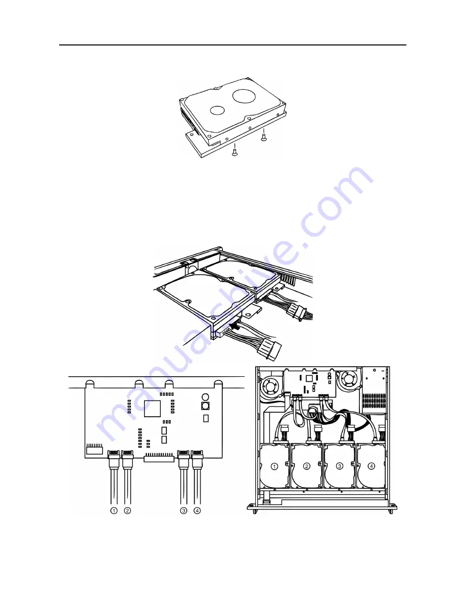
Place the hard disk drive on the SATA HDD carrier and attach it firmly with the screws. 


NOTES:  

  There is no need to change the master/slave jumper settings.


  The front and rear of the carrier are not the same.  Center the hard disk drive on the carrier. 

 
4.


Attach the SATA HDD carrier assembly to the unit base and screw it down with the pan head screw. 

 
5.


Connect a power cable and SATA cable to each hard disk drive.  The SATA cables should be connected 
in the order shown. 


NOTES:  

  Connect the cables tightly paying attention to the cable orientation.


  If the SATA cables are not connected in order, the HDD indicator LEDs will not match the HDD operation. 

Summary of Contents for DMR-104

Page 1: ......

Page 2: ......

Page 3: ...NCE AT THEIR OWN EXPENSE WARNING CHANGES OR MODIFICATIONS NOT EXPRESSLY APPROVED BY THE PARTY RESPONSIBLE FOR COMPLIANCE COULD VOID THE USER S AUTHORITY TO OPERATE THE EQUIPMENT THIS CLASS OF DIGITAL APPARATUS MEETS ALL REQUIREMENTS OF THE CANADIAN INTERFERENCE CAUSING EQUIPMENT REGULATIONS The information in this manual is believed to be accurate as of the date of publication We are not responsib...

Page 4: ...has been damaged B If liquid is spilled or objects have fallen into the equipment C If the equipment has been exposed to rain or water D If the equipment does not operate normally by following the operating instructions adjust only those controls that are covered by the operating instructions as an improper adjustment of other controls may result in damage and will often require extensive work by ...

Page 5: ...External Storage iii Table of Contents Chapter 1 Introduction 1 Features 1 Package Contents 1 Specifications 1 Rear Panel 2 Front Panel 2 Chapter 2 Installation 3 HDD Models 3 Installation 3 DVR Connection 5 ...

Page 6: ...Operating Instructions iv ...

Page 7: ...rd disk drives are already installed in the unit WARNING ROUTE POWER CORDS SO THAT THEY ARE NOT A TRIPPING HAZARD MAKE CERTAIN THE POWER CORD WILL NOT BE PINCHED OR ABRADED BY FURNITURE DO NOT INSTALL POWER CORDS UNDER RUGS OR CARPET THE POWER CORD HAS A GROUNDING PIN IF YOUR POWER OUTLET DOES NOT HAVE A GROUNDING PIN RECEPTACLE DO NOT MODIFY THE PLUG DO NOT OVERLOAD THE CIRCUIT BY PLUGGING TOO MA...

Page 8: ... when the unit is connected to a DVR Power Switch Turns the unit on or off Power Connector Connect to a power outlet using the power cord FRONT PANEL Power LED The LED is lit when the system is operating HDD LED 1 to 4 A green LED is lit when a SATA hard disk drive is installed A red LED is lit when data is transferring to or from the unit Green and red LEDs flicker when any error occurs in the in...

Page 9: ...te ST3500830SCE Western Digital WD5000AVJS Hitachi HDS721050CLA362 750GB Seagate ST3750840SCE Western Digital WD7500AVCS 1TB Seagate ST31000340SV Western Digital WD10EVCS 2TB Hitachi HDS722020ALA330 NOTE The list is subject to change without notice Ask your dealer or distributor for the latest list INSTALLATION Install the SATA hard disk drives maximum of 4 following these instructions 1 Remove sc...

Page 10: ...enter the hard disk drive on the carrier 4 Attach the SATA HDD carrier assembly to the unit base and screw it down with the pan head screw 5 Connect a power cable and SATA cable to each hard disk drive The SATA cables should be connected in the order shown NOTES Connect the cables tightly paying attention to the cable orientation If the SATA cables are not connected in order the HDD indicator LEDs...

Page 11: ... cable to the eSATA port on the rear panel of the storage unit and the other end to the eSATA port on the rear panel of the DVR 2 Connect the power cord to the storage unit and to the power outlet and turn on the power switch on the rear panel of the storage unit 3 Connect the DVR power cord and turn on the DVR system CAUTION Make certain that storage unit s power switch is turned on before turnin...

Page 12: ... Exclusive distribution through specialised trade channels only Videor E Hartig GmbH Carl Zeiss Straße 8 63322 Rödermark Germany Tel 49 0 60 74 888 0 Fax 49 0 60 74 888 100 Technical changes reserved www videor com Copyright by Videor E Hartig GmbH 06 2011 ...

Reviews: