Electrical Installation
WirelessHART Fieldgate SWG70
26
E Hauser
Internal wiring
The Ethernet socket is wired to the Ethernet terminal block. The internal wiring may not be
modified.
5.4
Connecting to RS-485
Fieldgate SWG70 is equipped with a fully galvanic isolated RS-485 interface. A second
RS-485 terminal block allows several Fieldgates to be connected through a daisy chain.
A terminating resistor is required at each end of the RS-485 cable. If the RS-485 cable is not
routed to other devices (no daisy-chain connection), activate the terminating resistor using
the corresponding DIP switches in the fieldgate. See Chapter 6.1.3 "DIP switches" on page 31.
NOTICE!
• The maximum length of the cable from the Fieldgate is 1200m (at reduced
communication speed).
• Use shielded twisted pair (STP) cables only.
• If the cable shield is grounded, only connect the grounding to one cable end. This avoids
potential equalization currents.
• Ensure adequate strain relief for the cables.
• Pay attention to the bending radii of the cables. Do not drop below the permitted bending
radii.
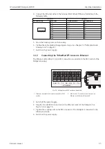
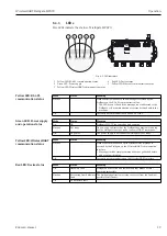
Fig. 5-5: RS-485 interface
Pin Numbering
Connector
Signal
Internal Wire Colors
Pin 1
TX+
Yellow
Pin 2
RX+
White
Pin 3
TX–
Orange
Pin 4
RX–
Blue
3
4
2
1
1 First RS-485 connection
2 Second RS-485 connection for daisy chaining
KL1
KL2
KL3
KL4
+24V
+24V
0V
0V
LINE1
LINE2
A
B
SHD
RS485
T1
T2
RX– RX+ TX– TX+
ON
OFF
SHD
A
B
SHD
RS485
ETHERNET
KL5
KL6
A
B
SHD
RS485
A
B
SHD
RS485
1
2


